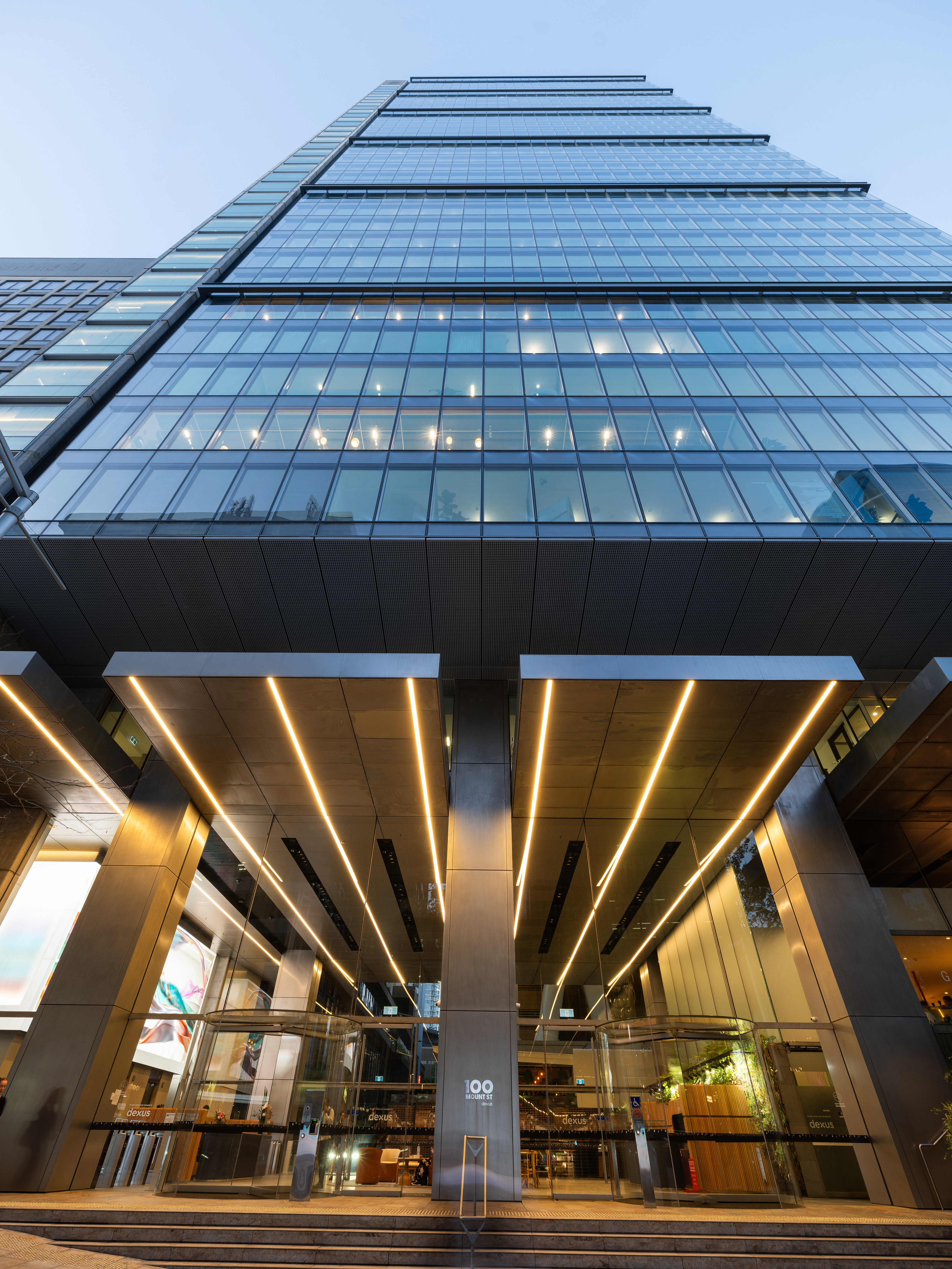
mount100internallobby-2235
100 Mount Street, North Sydney

Tenant Information Manual

Building Technical Specifications

Premises Design Guidelines

About the Premises Design Guidelines
The Premises Design Guidelines provide information for tenants, consultants and contractors carrying out works at the Building in relation to the following:
  • Mechanical Services
  • Electrical Services
  • Fire Services
  • Hydraulic Services, and
  • Lifts.

The Premises Design Guidelines must be read in conjunction with the Tenant Guidelines, in particulararticular the section with the heading Works Guidelines.


It is essential that the design parameters in this document are followed to ensure that works are not designed or carried out in a way that adversely impact the performance of the Building.


References and Definitions in the Premises Design Guidelines
Where any codes or standards are referenced in this document, the most current version of that Code or Standard is to be applied.


Capitalised words have the meaning given in the Tenant Guidelines.


Certification of works carried out at the Building
Prior to occupation of the Premises and within 21 days of completion of works the following documents must be provided to Building Management:
Certificate of Classification / Interim Occupation Certificate or Occupation Certificate or equivalentlent

  • Certificates of Compliance for all relevant services, and

  • Fire Safety Certificates (as applicable).

If the above documentation is not provided to us we may obtain it at the expense of the Tenant.

Electrical Isolation and Equipment

Isolation of electrical supply on the switchboards is only to be carried out by a qualified/authorised Contractor after we have given approval.

Works to the tenant distribution boards are also to be carried out by a qualified/authorised Contractor.

Main switches, circuit breakers or fuses must be tagged, with an approved tag stating reasons for isolation and signed by the authorised Contractor.

All equipment must be fully tested prior to the tag being removed and the circuit energised. Only the Contractor who tagged the equipment may authorise the removal of the tag and energising of the system.

Structure Cutting & Coring

The Contractor must obtain an Excavation Wall and Floor Penetration Permit prior to carrying out any of the following:

  • structural cutting

  • coring

  • drilling

  • chasing of walls, and

  • slabs for conduits/pipework.

Approval is required from Building Management prior to any coring of slabs.

Prior to the commencement of any drilling, digging or cutting activities on site the Contractor must establish if any services or structural impairment will be affected by the activity. All pods and curtain walls are to be reviewed and approved by structural engineer peer review.

The Contractor must not chase block walls where conduits can be slotted in from the top and turned out at the base.

Costs

The Tenant is responsible for any, and all, costs associated with works, including:

  • costs arising from services associated with works, including costs of services providedby the Approved Contractors and Consultants

  • costs incurred by the Landlord in assessing plans and specifications.

  • costs or charges due to Authorities, and

  • non-compliance with the Works Guidelines or these Premises Design Guidelines by theTenant or anyone carrying out works or services on the Tenant’s behalf.

mount100exterior-4186

Mechanical

Authorities, Codes and Standards
Mechanical services must be designed, documented and installed to the following standards:
Code/Standard
Description

NCC/BCA

National Construction Code / Building Code of Australia

AS 1668.1:1998

The use of ventilation and air conditioning in buildings – Fire and smoke control in multi-compartment buildings

AS 1668.2:2012

The use of ventilation and air conditioning in buildings – Mechanical ventilation in buildings

AS 3666.1:2011

Air handling and water systems of buildings – Microbial control – Design, installation and commissioning

AS 2107:2000 Acoustics – Recommended design sound levels and reverberation times for building interiors
AS5601 Gas Installations
Any codes and standards required by the following:
  • Jemena Gas Fitting Rules
  • Sydney Water Corporation, and
  • any fire engineering reports (as relevant).
Mechanical Design - Base Building Provisions
Design Ambient Conditions
Summer

Dry-Bulb Temperature 32.5 (°C) AHU coils; 24.0 (°C) cooling towers

Wet-Bulb Temperature 23.0 (°C)

Winter

Dry-Bulb Temperature 7.0 (°C) saturated

Relative Humidity 40-60 (%)

Design Indoor Conditions
Normal Business Hours 8am to 6pm Monday to Friday (excluding public holidays)
Zones Per Floor varies
Perimeter and internal zone size 15m2 perimeter, 20m2 centre
Summer

Dry-Bulb Temperature 22.5 (°C) + 1.5 (°C)

Relative Humidity 40-60 (%)

Winter

Dry-Bulb Temperature 22.5 (°C) + 1.5 (°C)

Relative Humidity 40-60 (%)

Building Envelope
Glare and solar control via closed cavity facade
Glazing SC 0.12
Glazing U-value 1.8
Mechanical Systems
Type/Details Floor-by-floor air handling system providing conditioned outside air, and centralised hydronic system servicing perimeter and centre zone active chilled beams
Plant Location AHUs at each floor; chillers and boilers at Level 36
Control System Central BMCS utilising Direct Digital Controllers
Internal Loads
Lighting 1.5 (W/m²) per 100 lux
Equipment 15 (W/m²)
Population Density 1:10
Ventilation
Outside Air (l/s/person)
Toilet Exhaust the greater of 10 (l/s/m2) floor area or 25 (l/s/fixture)
Kitchen Exhaust two 2,500 (l/s) commercial kitchen exhaust shared across building
General Exhaust 200 (l/s)
Tenant Supplementary Systems
Tenant Condenser Water
Water Temperature 31 – 36.5 (°C)
Heat Rejection to Condenser Water 33 (W/m²)
Total System Capacity 25 (kW/m2) NLA
Note: Condenser water temperatures are 31 (°C) supply & 36.5 (°C) return.

General Description of Mechanical System

100 Mount Street has been designed to meet Premium Grade commercial development, as defined by the Property Council of Australia (PCA) Guidelines to Office Building Quality.

Maximum Water Allocation Per Floor 1.72 (l/s) low-rise; 1.78 (l/s) mid-rise; 1.87 (l/s) high-rise
Duty/Standby Pumps and Heat Exchangers
Take Off Ø65 (mm)
Ventilation
Supplementary Outside Air 0.3 (l/s/m2) per floor; in-take louvre sized for a total of 0.75 (l/s/m2)
Supplementary General Exhaust 0.1 (l/s/m2) per floor; take-off sized for 0.25 (l/s/m2)
Supplementary Toilet Exhaust 0.1 (l/s/m2) per floor; take-off sized for 0.25 (l/s/m2)
Supplementary Kitchen Exhaust share of building system (2x2,500 l/s)

Base building air conditioning consists of floor-by-floor air handling system to provide conditioned outside air, and centralised hydronic system serving active chilled beams. On floor plant rooms are located at the north-west and south-west cores adjacent to the bathrooms


Cooling Plant

Chilled water is generated by water cooled high efficiency chillers configured to maintain 60% peak cooling should the largest chiller be out of operation for maintenance or failure. Control systems stage the operation of all chilled water plant to ensure peak efficiency and performance at all loads.


Chillers run on refrigerant with zero ozone depletion potential. Heat produced by chillers (water cooled) is rejected to the atmosphere by cooling towers located on the roof (Level 36)


Heating Plant

Two gas fired high efficiency modular heating generators are used to generate hot water for space heating. The system is designed to maintain a minimum of 60% heating capacity when one heating generator is out of operation for maintenance or failure.


Hot and chilled water is reticulated to various parts of the building via variable flow circuits.


Pumps are fitted with variable speed drives (for variable flow systems only) and high or premium efficiency motors.


Ventilation
All mechanically ventilated areas including toilets, tearooms, cleaner’s rooms, garbage room, plantrooms, grease arrestor room and storerooms are ventilated in accordance with the AS1668.2 2012


Outside Air
Conditioned outside air is provided via AHUs located on each floor.


High quality air filters (in compliance with AS1324) are utilised in air handling units. The main and pre-filters have minimum standards equivalent to type G4 + F7.


All Fan Coil Units have G4 filters; supply ventilation fans have F7 filters and all other miscellaneous supply ventilation fans have G4 filters.


Tenant Condenser Water System
A dedicated tenant condenser water circuit with tee-off’s adjacent to the male bathroom entry at each floor has been provided to cater for maximum total cooling capacity equivalent to 25W/m2 NLA (33W/m2 heat rejection) for office levels.


Tenants must provide all details regarding the condenser water usage rates for each package unit to Building Management before works commence.


All water supply pipework must reticulate within the Premises. Tenant condenser water flow and return lines to the riser must be suspended independent of all other services and be run so that they do not prevent the removal of ceiling tiles, light fittings, smoke detectors, or any other services.


Flexible hoses for final connections to Tenant’s supplementary air conditioning units are not permitted. As such units can only be suspended from acoustically insulated brackets fixed to the side of beams.


The condenser water pipework, supplementary units and associated equipment are to be designed such that they do not create index runs in any location and do not increase the pressure drop above the design intent of the condenser water system.


Connection to the Tenant Condenser Water System is subject to agreement by Building Management. The Tenant is responsible for all works, cleaning and maintenance beyond the floor valve connection take off point.


Supplementary Outside Air System
Provision of supplementary outside air is provided via on-floor AHU located in the south-west core and is sized to provide 0.3 L/s/m2 for each floor. The on-floor air intake louvre is sized for a total of 0.75 L/s/m2. The 0.3L/s/m2 supply air is conditioned and dehumidified.


The tenant supplementary outside system has been designed to allow for CO2 control to modulate the outside air delivered based on space occupation. It is recommended that this strategy is adopted as part of the tenant’s design. As part of this strategy CO2 sensors are required to be installed in each space served from the tenant supplementary outside air system. The control of the tenant supplementary outside air AHU is programmed that the return air and outside air dampers modulate to maintain maximum CO2 levels within the spaces served.


Should the tenant wish to operate the system as a 100% outside air system, ductwork is required to be installed between the outside air facade louvre and the tenant supplementary outside air AHU intake within the on-floor AHU southern plantroom. The base building BMCS contractor is required to be engaged for any controls programming and/or commissioning of the tenant supplementary outside air AHU.


Supplementary General Exhaust System
One general exhaust riser has been provided for supplementary tenancy requirements. The system is sized for 0.1 L/s/m2 per floor with capped branch ducts on the floor sized for a total of 0.25 L/s/m2. The system is fitted with a variable speed fan to conserve energy when the maximum air quantity is not required.


Connection to the system is subject to agreement by the Building Management. The Tenant is responsible for all works, cleaning and maintenance beyond the floor exhaust take off point.


Supplementary Toilet Exhaust System
One supplementary tenant toilet exhaust has been provided and sized for 0.1 L/s/m² per floor, with floor take-off branches sized for a total of 0.25 L/s/m².


Supplementary Kitchen Exhaust System
Two kitchen exhaust systems including ducting, shaft and fan are provided to each core. Two systems are provided with a maximum capacity of 2,500 L/s per system. One tenant in the high rise is able to connect to the southern riser and one tenant in the low and mid-rise is able to connect to the northern riser.


Systems comply with AS1668. Extract hood, and makeup air systems are to be provided by the tenant. Makeup air riser has been provided in the core riser


Premises Controls System and Logic

The Premises controls system must have no impact on the base building operations and must meet the following minimum criteria:

  • Supplementary air conditioning unit control must be able to supplement the control of space conditions maintained by the Building Management and Control System (BMCS). At no time will the supplementary unit operate in opposition to the base building system, and as such no Tenant supplementary units will be permitted in open office areas without prior approval from Building Management.

  • Relocation of base building thermostats are to be clearly documented and submitted for approval. In the event of the supplementary system and base building serving the same area, base building thermostats must be excluded from set point calculations. Works should ensure that there is no impact on the base building operations.

  • The base building temperature sensors/controller signals in areas served by the Tenant’s packaged a/c units should be deselected from the overall base building supply air temperature control. The areas will operate under local control of the terminal unit controller but will not have the capability to override the central plant operation.

  • All equipment, and software, must be capable of handling, and interpreting, time/day/year dates (including leap years) indefinitely, from the present date, without error.

  • All equipment and components including software, firmware and controls must conform to the requirements of Australian Standard HB104 or British Standard PD2000.


Building Monitoring and Control System (BMCS)

The Building Management Control System (BMCS) provides control of the building Mechanical HVAC systems and provides interfacing and monitoring of the Electrical, Hydraulics, Lighting, Security, Fire, Lifts and the blind controls to deliver a modern state of the art building that is capable of not just operating efficiently but to also have the capability to measure energy consumption to meet the highest industry standards. It collects data for performing trend analysis, energy analysis and daily alarms for the building operators to function a well-balanced building by improving efficiency without jeopardising occupancy comfort levels. The proposed BMCS (Metasys) & Energy Monitoring System (JEM) at 100 Mount Street will be designed around the latest generation of Johnson Controls Metasys System Extended Architecture which uses open architecture direct digital control technology with distributed intelligent IP controllers. The Base Building Analytics system provides monitoring of BMCS and Energy Management data points and collects trending of usage of HVAC equipment. The analytics software provides insights into operations and performance to improve energy efficiency and tenant conditions.


Operator Workstation

The workstation uses a standard web browser to access the network so proprietary software is not required. The user interface (including graphics) as well as the on-line configuration software is embedded in the NAE. Multiple concurrent users can access this data anywhere on the network using a standard web browser (Microsoft IE 10.0+) and view current field devices and point status, manage BMCS alarms, command or adjust point values and edit the NAE / NIE database on-line. Remote access to the BMCS is via the Internet using a standard web browser (IE, Chrome, etc) which provides full password and security access to the system. The BMCS server, is located in the Head End Room on level B1, with the operator workstation located in the adjacent Security Office.


After-Hours Air-Conditioning Interface

The After-Hours reports will record the After-Hours usage of each tenant in each functional area or individual floor plate as a minimum to the requirements of the NABERS Protocol. AHAC will be requested via a tenant web portal. There will be 4 no. zones per floor for the purpose of AHAC. Tenants will have a graphical interface showing their floor to select which zone is required. Start and finish time input will be through this interface.

All AHAC requests will be logged with date, username, activation time and duration. An automated AHAC report will be generated monthly and emailed to selected recipients. The user will have the option of entering cost/hr for AHAC usage per tenant which will then generate a monthly after-hours invoice.

The details and costs of this system are available from Building Management.


Premises Considerations

Tenants adding components must ensure the BMCS system is fully updated to reflect additional devices. All Premises changes and variations to the BMCS, both hardware and software, in its entirety, must be performed by an Approved Contractor. All BMCS information must be forwarded to the Analytics Contractor to map and program into the Base Building Analytics Software.

Interlocks must be provided to prevent base building air conditioning control conflicting with premises PAC controls.


Relocation and Addition of Chilled Beam(s)

When connecting new chilled beams to the existing chilled water system, the following procedures must be complied with at the tenant’s expense.

  • The entire floor system must be disconnected from the high temperature chilled water risers and drained.
  • All new pipe connections must be done in a manner that prevents any contaminants from entering the pipework system – hot tapping is prohibited. Ideally existing pipe should be cut and cleaned carefully around the cuts before fitting an appropriate Tee. The methodology to be used must be approved by the building design engineer before any works are undertaken, and the cut pipe must be inspected by the building owner’s representative and the nominated base building independent commissioning agent before any fittings are added.
  • All new chilled beams and their associated pipework must be flushed (see below for methodology) prior to connection to the existing pipework system and connection approval must be obtained from the building owners representative.
  • With the floor pipework still disconnected from the main risers, refill the pipework and then shut all PIC and bypass valves on the existing system. Also shut the Pic valves serving any new chilled beams, but make sure the respective bypass valves are open.
  • Flush the floor pipework system until clean (as per the methodology below).
  • Once approval by the building owner’s representative and the nominated base building independent commissioning agent has been obtained, the system may be reconnected to the chilled water risers

When disconnecting/reconnecting any existing chilled beams, new washers are to be installed on both supply and return flexible lines. The washer specification is to that as provided by building management.


General Works Conditions – Mechanical
Thermostats are to be located in the areas they serve.


Where it is determined that the Tenant will have an increased need for air conditioning outside of the Building Service Hours (for example, for call centres and operations centres) the Tenant must install Tenant supplementary units so as to minimise energy use of the base building plant and reduce costs to the Tenant.


All supplementary air conditioning units serving areas other than computer rooms must have timer switches to allow the unit to run for a maximum time of 1 hour maximum before turning off. The controls should be manual on and automatic switch off based on a timer.


All supplementary units are to be connected to the BMCS.


Where it is necessary to remove or relocate any existing mechanical infrastructure, including mixing boxes, thermostats and/or controls the Tenant will require approval from the Approved Consultant for Mechanical Services so that the performance of the existing design is not affected.


Where it is necessary to remove or relocate any existing mechanical infrastructure, including mixing boxes, thermostats and/or controls the Tenant must engage the relevant Approved Contractors to complete the works.


Any amendments must be pre-approved by Building Management and must be properly installed or removed and connected or disconnected from the BMCS system by the Approved Contractor for Mechanical Services.


All ductwork, rigid and flexible must be supported from the under-side of slab. No ductwork must be supported on the ceiling grid. Similarly, no ceiling grid or other service is to be supported from the ductwork or pipework.


All occupied areas/rooms in particular meeting rooms and function rooms must be provided with minimum outdoor air rates in compliance with AS 1668.2 - 2012. All calculations and documentation must be presented to Building Management to demonstrate compliance with minimum outside air rates.


Appropriate sizes, numbers and locations of access panels must be provided for the maintenance services of all mechanical plant, dampers, VAV boxes and duct heaters etc. Access panels must be sized so as to allow safe access to all equipment and be of a standard similar to that throughout the Building.


All condensate from the additional package unit(s) is drained to tundishes/floor wastes via condensate drainage pipes. Where falls are inadequate to facilitate effective drainage a suitable pump out system must be installed.


Where condensate pumps are utilised, these are to be interlocked with the operation of the associated air conditioner to prevent flooding on failure and fitted with an alarm. Condensate pump are to include drip trays and water leak detection in line with supplementary units.


Where computer room type units are used the condensate / humidifier waste must drain to a cooling tank prior to being pumped. The supply air outlets (and/or return air inlets) that are being relocated must be rebalanced. The Tenant must present the new commissioning figures of the whole Premises to Building Management on the completion of the works.


A solenoid valve is to be provided to each of the condenser water flow lines to the package air conditioning units to avoid circulation of condenser water through these units when they are not operating.


Where supplementary systems are supplied with outside air from the Tenant’s supplementary outside air system, motorised dampers are required to shut off the supplementary air supply when the associated unit is not running.


Each supplementary air conditioning unit must be electrically connected to the Tenant’s non-essential distribution board. Each unit must be clearly numbered on the outside of the unit and identified on the distribution board. All controls associated with package units must be electric/electronic type.


No modifications to chilled, heating or condenser water loops are permitted without the approval of the Approved Consultant for Mechanical Services.


During works all return air riser take-offs and chilled beams on floors affected by the works must be covered with an appropriate filter media to minimise dust in the return air plenum and ductwork.


Tenancies on multi-tenanted floors may require either acoustic security transfer ducts across the Premises dividing partition or return air grilles in the Premises wall to the core corridor and corridor ceiling grilles, to allow the return air from the Premises to leave the Premises and return to the false ceiling level to the return air duct.


Areas which are highly partitioned or have floor to slab partitioning must have sufficient return air grilles to allow return air to traverse the above ceiling space when partitioned doors are shut.


The VAV boxes and air diffusion equipment layout must be designed and installed to allow correct VAV modulation and thus avoid hot spots, under-sized zones, poor temperature sensing and the like. Ductwork modifications will be minimised to maintain straight duct runs and resultant pressure loss through system. Use of flexible duct must be kept to a minimum with bends kept gentle (bend radius >1.5 diameters).


Prior to commencing works, the Tenant must provide a detailed plan showing the location of all staff, equipment, and lighting to determine the heat load and the usage of all areas. These plans must be provided to the Approved Consultant for Mechanical Services for approval.


Connection to the dedicated condenser water system for package units is generally available subject to the following:

  • the provision of details of the proposed installation for review and approval

  • the provision of details of the equipment including the model and manufacturer, the output in kilowatts and the water flow requirements, and

  • confirmation that units will be set-up to run, to suit tenant needs, for only as long as is necessary.


The pipe work to the unit must include the following:

  • isolating valves on the flow and return pipelines

  • Head pressure modulating control valve

  • an electrically operated solenoid or motorised valve in the flow to the unit activated only when the compressor starts

  • a fine mesh strainer in the flow pipeline to the unit

  • a "STAD" water balancing valve in the flow to each unit

  • a “STAD” water balancing valve at the take-offs on each rise to allow flow checks to be carried out

  • a mechanical interlock, which disables the refrigeration component on loss of condenser water flow and resets automatically on return of flow

  • where the Tenant is not a whole floor tenant there must be a set of capped off isolation valves left for future connection by other suite tenants, and

  • straight pipe runs that minimise system pressure losses.


All drawings submitted must include the following:

  • all valving as noted above in the approximate area of it intended or actual location, and

  • all pipe work shown in its intended or actual location and dimensions.


Building Management may carry out spot checks on Premises condenser water flow rates at any time. Should the checks show that the flow rate exceeds that agreed between the Tenant and the Building Management Building Management will require the Tenant to return the flow to the agreed level or alternatively pay for the excessive use at agreed rates.


Where existing air and water systems are to be modified as part of the works the following must be undertaken prior to commencement of the work and submitted to the Building Management for review:

  • investigation and recording of existing air and water quantities

  • system pressures and fan operating currents and pressures, and

  • smoke control and stair pressurisation systems.

The Tenant is responsible for ensuring that the air distribution is suitable for Premises loads.


Premises Commissioning

Following the completion of the Premises ductwork changes, the following commissioning procedures associated with the base building systems, must be completed by the Tenant:

  • testing and commissioning of all modified mechanical systems as well as smoke control and stair pressurisation systems, and

  • Re-commissioning and re instatement of all existing systems must be undertaken to ensure that the balance and performance of base building systems is not detrimentally affected.

Following the completion of works, the following commissioning, testing and proving procedures associated with the base building systems must be undertaken by the Tenant:

  • re-testing of stairwell pressurisation systems to ensure compliance and provision of certification of the systems performance equivalent to the annual Fire Certification for the floors affected

  • re-testing of all fire mode operation of central plant including dampers in fire affected and non-fire affected modes and provision of certification of the systems performance equivalent to the annual Fire Certification for the floors affected

  • re-establishing of the floor supply air static pressure and air quality for each zone at full cooling

  • Recommissioning of all VAV and mixing box terminals including maximum and minimum air quantities and rebalance of heating water flows. Note this includes updating the BMCS parameters within the controllers

  • All new and existing chilled water pipework being thoroughly flushed in accordance with BSRIA application guide AG1/2001.1: Pre-Commission Cleaning of Pipework Systems or its equivalent. The tenant is to provide flushing and water quality test records to Building Management for approval prior to connection to the building systems.

  • balancing supplementary condenser water system where supplementary air conditioning systems are installed

  • demonstration that air flows, water flows and system operation to the satisfaction of Building Management

  • Calibration certificates including offsets for all space temperature sensors

  • Confirm that all BMS and Energy data points are mapped and communicating on the Base Building Analytics Software

  • provision of technical data for all supplementary systems, testing and commissioning data and as installed drawings in hard copy and AutoCAD 2000 format for inclusion in the buildings Operating & Maintenance Manuals, and

  • testing of base building systems and other tenanted areas is to be undertaken outside of Building Service Hours or at times agreed with Building Management to cause minimum disruption to other tenants.

Air balancing and system testing must be undertaken by a qualified contractor.


All commissioning to be undertaken in accordance with ASHRAE Guideline 1 and CIBSE Commissioning Code A, B, C, M, R and W.

Electrical

Authorities, Codes and Standards

Electrical Services must be designed, documented, and installed to the following standards:

Code/Standard
Description
NCC/BCA National Construction Code / Building Code of Australia
AS 1680 Interior and workplace lighting
AS 1768 Lightning protection
AS 2293 Emergency escape lighting and exit signs
AS 3000 Electrical installations - SAA wiring rules (and associated codes nominated therein)
AS 3008.1.1 Electrical installations – Selection of cables
AS 3013 Electrical installations – Classification of fire and mechanical performance of wiring system elements
AS 3439 Low-voltage switchgear and control gear assemblies
AS 2201.1 Intruder Alarm Systems - Part 1 - Systems Installed in Client’s Premises
AS 2201.3 Intruder Alarm Systems - Part 3 - Detection Devices for Internal Use
AS 2201.4 Intruder Alarm Systems - Part 4 - Wire Free Systems for Client’s Premises
AS 2201.5 Intruder Alarm Systems - Part 5 - Alarm Transmission Systems
AS 3080 Telecommunications installations - Integrated communications cabling systems for computer and commercial premises
AS 2053 Conduits fittings for electrical installations
AS 2834 Computer Accommodation
AS 3000 Electrical installations - SAA wiring rules (and associated codes nominated therein)
AS 3015 Electrical Installations - Extra-low voltage DC power supplies within public telecommunications networks
AS 3084 Telecommunications Installations - Telecommunications pathways and spaces for commercial buildings
AS 3085 Telecommunication installations - Administration of communications cabling systems
AS 3100 Approval and test specification - General requirements for Electrical Materials and Equipment
AS 3260 Approval and test specification - Safety of Information technology equipment including electrical business equipment
AS 4933.1 Digital Television – Requirement for Receivers, Part 1: VHF/UHF DVB-T television broadcasts
NSW Service Installation Rules, and
Any codes and standards required by Authorities.
Power Supply - Design and Performance Criteria Substation
Substation
Substation Arrangement
Capacity (kVA)
Main Switchboard
Number Two (2)
Details MSB-1 (House) 2,500 (A) MSB-2 (Tenant) 3,000 (A)
Provision for bulk metering of all premises floors
Design Tenant power allowances 60 (VA/m²) NLA undiversified
House Distribution Boards
Location Riser in south-west corner of L3, L6, L9, L12, L15, L18, L21, L24, L27, L30 and L33
Details Form 1 dead front type
Rating 80 (A)
Tenant Distribution Boards
Location Riser in south-west corner of each commercial floor
Details Form 1 dead front type; special provision for four tenant DBs per floor
Rating 160 (A)
Lighting - General Information
Lighting
Design lighting level 320 (lux)
Power density (W/m²)
Premises lighting details
House lighting details
Emergency and exit lighting system
Standby Power - General Information
Generators
Generators 2 x 2.25 (mVA)
Type of drive SCADA
Fuel storage capacity 25,000 (L)
Run capacity 24 (hours/full tank)
Base Building
Standby power capacity 100 (%) diversified
Premises
Tenant provision 160 (A)

Substation
The building electricity has been provided from an onsite Ausgrid chamber substation housed at B1 Level. The substation has 3 transformers totalling 5,500Amps


Main Switchboard
The main switchboards are located at Basement 2 and are provided with 25% spare space including poles for separate submains for connection of future tenant UPS submains or computer room A/C units.


Surge protection has been provided to all main switchboards. Automatic transfer switches are included for diesel power supplies.


Power Factor Correction
Power factor correction equipment is installed, to maintain the power factor of house services to a minimum of 0.98, at all times. Spatial provision for a single tenant power factor correction equipment has been provided.


House Distribution Boards
House DBs are located in the south-west corner electrical riser on Levels 3, 6, 9, 12, 15, 18, 21, 24, 27, 30 and 33. Each DB connects house services on the floor and each neighbouring floor above and below it.


Premises Distribution Boards
A Tenant DB is provided to each floor in the south-east corner electrical riser. The riser includes spatial provision for up to four tenant DB’s. The installed Tenant DB is rated for 160A capacity and connected to the main bus bar by 200A tee-box. Changes to Distribution Schedules are to be provided in both hard and soft copy, with hard copy displayed at the TDB.


Lighting Systems & Fittings
Lighting to office areas are design to 320 lux in accordance with AS/NZS1680 is provided to the office area of each floor by a combination of LED troffer and suspended strip fittings with DALI system fully addressable dimmable ballasts managed through a central control system.


Automatic lighting control system complete with motion sensors is provided throughout as well as daylight harvesting to perimeter zones.


Emergency Lighting Systems
Emergency and evacuation and exit signs complying with the requirements of NCC 2015 and AS2293.1 are installed throughout the building. Testing facilities are via a computer monitored system with automatic testing capability.


All amendments to the emergency light systems must be connected to the base building and commissioned by the Base Building Contractor for Emergency & Exit Lighting. As builds RCP to be provided with labelling IDs to match Clevertronics database.


Standby Power Generation Systems
A Supervisory Control and Data Acquisition (SCADA) operates the standby power system and be responsible for the orderly distribution of standby power to the required essential and non-essential building loads.


The base building diesel generators are sized to achieve whole building realistic load back up including tenant use. Diversity factors based on realistic load profiles for commercial buildings have been used to size two 2.25mVa generators at Level 36.


Fuel storage capacity of 25,000L provides 24-hour generator run capacity.


Access Control and CCTV System
The building has been provided with an open protocol access control system, which controls access by proximity card or other approved means to all areas of the building. The access control system is linked to the CCTV system and is capable of connecting to the internet for remote access and monitoring if required.


Base building CCTV system is high resolution and connected to a digital recording system, through IP system. The footage is stored on a digital recording system having a minimum capacity of 60 days. The power to the CCTV system is backed up with a UPS for a minimum of 1 hour.


Telecommunications Lead-ins

The building is serviced by multiple fibre data/internet carriers including:

  • NBN (FTTP – Fibre to the premises (floor))

  • TPG

  • Vocus

  • Telstra


Communication Network

A sophisticated Integrated Communication Network (ICN), also referred to as Converged Network, serves the building systems and operational needs. This network includes a fibre optic cable backbone. Both the fibre backbone and/or ICN have capacity to service tenant requirements. This includes renting fibre optic cable for vertical interconnect rather than hauling new fibre, building provided guest Wi-Fi in your tenancy, or other requirements that can be discussed.


Communication Risers

Two dedicated tenant communications risers are provided at each floor in the north and south core zone. Cable tray and cable is to be installed by the tenant. All riser penetrations are to be pre-approved. Post installation, all penetrations are to be fire sealed by the base building fire service contractor and certificate of compliance is to be provided.


Master Antenna Television System

An MATV backbone is provided with antenna and head end equipment connection available via the House Communications riser on each floor. The system is suitable for digital television signals and Pay TV connections (such as Foxtel).


Mobile phone cellular coverage Distributed Antenna System (DAS)

Mobile phone coverage within the building is achieved using a dedicated building system known as a Distributed Antenna System. The system is installed throughout the building including white dome antennas attached to the ceiling within the tenancy, lift lobbies and public areas.

A DAS is highly specialised equipment and cannot be dealt with by a standard electrician or builder. It is a significant investment for Dexus that needs to be protected. Two fit-out activities commonly impact DAS performance:
  • Modification or damage to antennas or cabling. Including placing antenna above the ceiling, or moving the antenna form their current location. Any faults can impact several floors above or below the source floor.
  • Interference on the system from nearby items including fit out materials and furniture (particularly metal). Typical issues come in the form of emergency lights, sprinklers, metal lockers, etc.
The following activities should be undertaken (at tenant cost) to minimise impact on the DAS:
  1. Fit out RCPs to be reviewed by Wireless Coverage Solutions (WCS) on behalf of Dexus to evaluate the impact to the system on a floor by floor basis. To limit impact WCS recommend a minimum distance of 300mm from a DAS antenna to other ceiling mounted services. Should ceilings types be changed (or removed altogether) in areas where antennas exist there will likely be works required to relocate these units, similarly with the construction of walls and partitions may require relocation or the addition of extra antennas
  2. WCS to provide formal feedback on the impact of proposed fit out changes and any associated costs with adjusting the DAS system to accommodate the intended fit out.
  3. Post Completion of fit out (and DAS works if required) the relevant floors require a PIM test to validate that mobile coverage has been maintained.


Premises Considerations
The Tenant must provide details of all new connections to switchboards for Premises users which must be submitted to Building Management for approval.


The Tenant must coordinate all connections to base building standby generator supply with Building Management. Note that an allowance of 60VA/m2 (undiversified) is available for the Tenant electrical loads. Any additional generator back up capacity is to be approved by Building Management.


The Tenant is to provide a maximum demand calculation for approval. If the Tenant load exceeds generator supply allowance, load shedding facility and logic is to be included in the works.


The Tenant sub mains are designed to provide power allowances as per the Design and Performance Criteria in the table above. Any additional load requiring Tenant specific additional sub mains from the unmetered sections of the main switchboard will be installed by the Approved Contractor for Electrical Services.

The following must be carried out by the Base Building Contractor for Electrical Services with the Contractor for the works in attendance:

  • Premises Lighting Controls Systems commissioning and integration of the Tenant system interface to the base building, and

  • Premises emergency and exit lighting commissioning and testing.

Where new UPS systems and generators are provided, ensure all details are submitted to Building Management for approval.


New equipment installed must comply with AS/NZS 61000.3.6.


Seal all penetrations and fire rate them where they pass through fire separations.


The Tenant must provide testing for phase balance and harmonic measurements for each Premises level.


The Tenant must ensure heavy equipment locations are confirmed with the Approved Consultant for Structural Services.


Ensure compliance of the emergency and exit lighting systems is always maintained during and after works are undertaken on the Premises.


Form 15A certification for all Emergency Essential Services, including a schedule showing dates when re-certification / testing is required with space for follow-up certificates.


All commissioning to be undertaken in accordance CIBSE Commissioning Code C, L and M.


Co-ordinate site location and approval for the mounting of all rooftop telecommunication services (such as microwave, laser, and other services) with Building Management.


Provide a minimum of RG6 quad shielded cable from the MATV distribution taps to Premises outlets as required. Ensure all unconnected system ports are terminated with 75-ohm terminating load. All work is to be carried out by the Approved Contractor.


Cabling

Inter-floor cabling must be labelled at every floor along its entire route using printed labelling to identify:

  • Origin

  • Destination, and

  • Company / contact details.

Where cables associated with works utilise a base building cable tray, they must be bundled together in an organised and spatially minimised configuration.


All cable routes that utilise base building cable routes must be submitted to Building Management for approval prior to installation.


All inter-floor and floor communications cabling associated with the Premises must be removed as part of make good works.
All horizontal communications cabling including MATV cabling associated with a particular premise must be removed as part of make good works.


Access Control Systems and CCTV
If the Tenant requires an access control system, the following items are to be provided by the Tenant:

  • a stand-alone access control system with no interconnection with the base building system, and


  • all access control equipment (including software and cabling).


The Tenant will apply for access control credentials from Building Management for both card format and programming in order to utilise base building readers without the need for separate credentials for the Premises system.


The Tenant may use a separate credential system; however, the base building card/credential will be required for base building access (including for the car park, lifts and access outside of Building Service Hours) so this is not recommended.


If the Tenant requires a CCTV system, it must provide a full stand-alone CCTV system with no connection to the base building system.

Fire

Authorities, Codes and Standards
Fire Services must be designed, documented, and installed to the following standards:
Code/Standard
Description
Code
NCC/BCA National Construction Code / Building Code of Australia
AS 2118.1:1999 Automatic fire sprinkler systems – General systems
AS 2118.6:2012 Automatic fire sprinkler systems – Combined sprinkler and hydrant systems in multistorey buildings
AS 2419.1:2005 Fire hydrant installation – System design, installation and commissioning
AS 2441:2005 Installation of fire hose reels
AS 2444:2001 Portable fire extinguishers and fire blankets – Selection and location
AS 1668.1:1998 The use of ventilation and air conditioning in buildings – Fire and smoke control in multi-compartment buildings
AS 1668.2:2012 The use of ventilation and air conditioning in buildings – Mechanical ventilation in buildings
AS 1670.1:2004 Fire detection, warning, control, and intercom systems – System design, installation and commissioning
AS 1670.4:2004 Fire detection, warning, control, and intercom systems – Sound systems and intercom systems for emergency purposes
Life safety systems information
Fire Detection System
Detection National Construction Code / Building Code of Australia 2015
Mechanical systems Automatic fire sprinkler systems – General systems
EWIS Automatic fire sprinkler systems – Combined sprinkler and hydrant systems in multistorey buildings
Fire Protection System Fire hydrant installation – System design, installation, and commissioning
Sprinklers Installation of fire hose reels
System description Portable fire extinguishers and fire blankets – Selection and location
Type The use of ventilation and air conditioning in buildings – Fire and smoke control in multi-compartment buildings
Hazard classification The use of ventilation and air conditioning in buildings – Mechanical ventilation in buildings
Design density Fire detection, warning, control, and intercom systems – System design, installation and commissioning
Sprinkler head type Fire detection, warning, control, and intercom systems – Sound systems and intercom systems for emergency purposes
Sprinkler response time
Hydrants
Description
Locations
Extinguishers
Type
Location
Emergency Evacuation
Egress description

Fire Detection System (smoke detection and fire fan controls)
A fire alarm and detection system is installed within the building and in accordance with the requirements of the NCC 2015, AS1670.1-2004, AS1668.1-1998 and the FRNSW.


The system incorporates smoke detection where applicable to initiate the smoke control system within the building and monitors all devices connected to the fire hydrants, fire sprinkler and fire pump systems. Thermal detectors are installed in shower rooms and areas where nuisance tripping of smoke detectors may exist.


The fire indicator panel is located in the fire control room at Lower Ground Level and is accessible via Spring St.


The system is connected to the fire brigade by a Grade 1 fire monitoring service to relay general fire alarms to the fire brigade.


The base building fire indicator panel has capacity for tenants to expand the number of detectors to AS1670.1 where inter-floor connections are proposed, for up to three consecutive floor inter-connections.


Emergency Warning and Intercommunication System
A Sound System and Intercom System for Emergency Purposes (SSISEP) (formally EWIS) is installed throughout the building.

The SSISEP is compliant with the requirements of the NCC 2015, AS1670.1-2004, AS1670.4-2004 and the FRNSW.


The SSISEP has provision for an increase of 25% to each floor or zone. The SSISEP panel is located in the fire control room.


The system incorporates break glass alarm points on each floor (adjacent to the fire stairs for use by the occupants for early warning, speakers for emergency broadcasting and warden intercom phones for fire brigade use in coordination of firefighting efforts.


Warden phones are located in the FHR cupboard adjacent to the Male Bathroom entry on each commercial floor.


Combined Sprinkler and Fire Hydrant System
A combined sprinkler and fire hydrant system is installed throughout the building to provide sprinkler protection and fire hydrant to NCC 2015 deemed to satisfy requirements which are compliance with AS2118.6-2012 and the Fire Engineered solution where applicable.


The water supply grade is a Grade 1 water supply in accordance with AS2118.1-1999, which includes a fire tank and a town main water supply.


Each level of the building is fitted with a monitored subsidiary stop valve to permit tenant fit out or alterations without affecting other occupied floors. Flow switch with remote test valve is fitted to each floor to provide indication of the fire affected level at the base building fire indicator panel. All devices are monitored by the fire indicator panel.


Fire sprinkler system to the retail areas accommodate relevant restaurant classifications as defined by AS2118.1-1999 for the Ordinary Hazard Category 1 (OH1) class system.


Carpark areas are protected to Ordinary Hazard Category 2 (OH2) class.


Fire Hydrants
Fire hydrants are installed in accordance with the requirements of the NCC 2015, AS2118.6-2012, AS2419.1-2005, AS2441-2005, Sydney Water and the Fire and Rescue NSW (FRNSW).


The base building provides fire hydrant risers with landing valves at the fire stairs for typical floors, reticulated in ring mains.
Future connection and extension of this fire hydrant service is part of the tenant’s works at the tenant's cost.


One on floor hydrants is required for open floor plate coverage. On floor hydrant location can be adjusted and/or additional installed by tenant as part of fit out if coverage is compromised by fit out.


Fire Hose Reels
A fire hose reel service has been provided throughout the site to comply with the deemed to satisfy provisions of Clause E1.4 of NCC 2015, AS2441-2005 and the requirements of Sydney Water. The fire hose reel system is supplied with water from the domestic cold water in accordance with Sydney Water requirements.


The base building includes fire hose reel risers with fire hose reels located adjacent to the fire stair exits at typical floor.


Future connection and extension of the fire hose reel services is part of the tenant’s works at the tenant's cost.


Fire Extinguishers
Fire Extinguishers to supplement other first aid fire equipment throughout the building in accordance with AS:2444-2001 and the BCA.

Each commercial floor is typically provided with:

  • one (1) 5kg CO2 extinguisher installed in the FHR cupboard adjacent to the male bathroom

  • one (1) 4.5kg A:B(E) powder extinguisher in the FHR cupboard adjacent to the goods lift


Premises Considerations

The Tenant’s fire services contractor must provide all temporary fire protection measures required by local or other regulatory Authorities during the entire period that works are being executed. Upon completion, temporary installations must be removed.

All penetrations in walls, floor and hydraulic, mechanical, electrical and fire cupboards, must be sealed. Any voids to penetrations must be filled with fire resistant pillows to maintain the specified fire resistant level (confirm with Building Management).

The following must be carried out by the Approved Contractor for Fire Services:

  • sprinkler alterations

  • drain downs, and

  • connection and modification of services to the Building smoke detection system.

All drawings in the fire control room and panel identification are to be updated to show any changes.


The efficient coverage and operation of the wet pipe sprinkler system must not be impaired by Tenant’s works.


The sprinkler system must be fully operational at the end of each working day. If a system is not operational, a security guard must be employed at the Tenant’s expense for the duration that the sprinkler system is not operational.


Control wiring to the BMCS is to be protected from mechanical damage. Should any damage occur, the connection will be repaired at the Tenant’s expense.


Building Management or the Approved Consultant for Fire Services is to witness the testing of the EWIS and Smoke Detection systems to ensure that it is fully operational at the completion of the works.


Commissioning

All commissioning to be undertaken in accordance with CIBSE Commissioning Codes.

Hydraulic

Authorities, Codes and Standards
Hydraulic Services must be designed, documented, and installed to the following standards:
Code/Standard
Description
NCC/BCA National Construction Code / Building Code of Australia
PCA Plumbing Code of Australia
AS 5601 Gas installations
AS 3500 Plumbing and draining
AS 2845.1 Water supply – Backflow prevention devices – Materials, design and performance requirements

Any codes and standards required by the following:

  • Sydney City Council


  • Jemena, and


  • Sydney Water Corporation.

Hydraulics - Provisions
Hydraulics Base Building
Soil Stacks Adjacent to DDA, female and male bathrooms on each floor
Waste stacks Riser in southern core cupboard
Potable water storage tank 52,000L tank located on Level 37
Potable cold water Riser in southern core cupboard
Potable hot water Riser in southern core cupboard
Hydraulics - Premises
Grease Stack Riser in southern core cupboard
Potable cold water Riser in northern core cupboard
Soil stacks Riser in northern core cupboard
Minimum WELs rating 4 stars

Sanitary Plumbing
The sanitary plumbing and drainage system generally picks up all fixtures and fittings within the Building to the town’s main.


The Tenant riser is located in the northern core riser.


Grease / Trade Waste Plumbing
Capped trade waste and vent branches are provided for kitchens within each rise of the building at the southern core for future extension and connection by tenant

Potable Cold Water
Valved and capped 25mm diameter connection (capped at northern core) has been provided on the cold-water supply for extension to the on-floor kitchens, kitchenettes, pantries and the like by tenants on each office floor of the building.


Cold water for retail tenants is individually metered by pulse type water meter is monitored by the BMCS for the billing purposes


Potable Hot Water
Valved and capped 25mm diameter connection (capped at southern core) has been provided on the hot water supply for extension to the on-floor kitchens, kitchenettes, pantries and the like by tenants on each office floor of the building.


Natural Gas Services
Valved and capped metered connections have been provided on the gas service in a nominated location for a kitchen (capped at the core) for extension to the proposed on-floor kitchen by the tenant.


The gas pipe branches are to be individually metered as part of the fit-out by the tenant


Premises Considerations
The Tenant’s connections to the building services must be balanced to prevent overloading of the water and waste system.


Membrane/ Tanking certificates will be required for all wet areas, bathrooms, kitchens showers etc.


All penetrations in walls, floor and hydraulic, mechanical, electrical and fire cupboards, must be sealed. Any voids to penetrations must be filled with fire resistant pillows to maintain the specified fire-resistant level.


The Tenant is to provide pressure reduction as necessary.


The Tenant is to install sub-metering that will record water use so quarterly reports can be prepared. The water usage and drainage costs will be charged to the Tenant.


Where provided and maintained by the Tenant, landscaped areas and planter boxes are to use drought tolerant species and avoid over-watering by manual or automatic irrigation systems.


Sanitary Ware Taps and Faucets
This section comprises details of the sanitary fixtures, taps and faucets incorporated within the site.


The following specified flow rate must apply to the installed fixtures in the Premises:
Taps / Basins – 3.5 L/min
Showers – 5.5 L/min
Toilets/ WC – 3.3 average ¾ dual flush
Urinals – 0.8 L/Flush


Acoustic insulation to a weighted sound reduction index (Rw) of 45 is required to all sanitary plumbing, soil waste and water service pipework within the ceiling space of the premises floor directly below.


Back flow prevention devices must be fitted to tenant plant items / dehumidification devices


Commissioning
Provide a Certificate of Compliance for all plumbing and drainage works to Building Management.


Commissioning Certificates for Premises thermostatic mixing valves and backflow prevention valves are to be provided to Building Management.


All commissioning to be undertaken in accordance with CIBSE Commissioning Codes.

Lifts

Number of Lifts/Type
Low Rise (Levels G - 14)
Mid Rise (Levels 14 - 27)
High Rise (Levels 27 - 35)
Car Park (Levels B6 - G)
Goods Lift (Levels B2 to 35)
Power System
Low Rise ‘Machine Room less’ (MRL)
Mid Rise Overhead Drive
High Rise Overhead Drive
Car Park MRL
Goods Lift MRL
Rated Load (kg; no of persons)
Low Rise 1,600kg; 21 passengers
Mid Rise 2,000kg; 26 passengers
High Rise 1,800kg; 24 passengers
Car Park 1,600kg; 21 passengers
Goods Lift 2,500kg; 33 passengers
Rated Speed (m/s)
Low Rise 2.5 m/s
Mid Rise 6.0 m/s
High Rise 7.0 m/s
Car Park 1.6 m/s
Goods Lift 3.5 m/s
Door Opening Dimensions
Low Rise 1,100 wide x 2,600mm high
Mid Riser 1,100 wide x 2,600mm high
High Rise 1,100 wide x 2,600mm high
Car Park 1,100 wide x 2,300mm high
Goods Lift 1,600 wide x 2,700mm high
Car Dimensions
Low Rise -1600 wide x1980 deep x 2840 high
Mid Rise - 1560 wide x 2350 deep x 2840 high
High Rise - 1830 wide x 1960 deep x 2840 high
Car Park - 1,700 wide x 2,000 deep x 2,600mm high
Goods Lift - 1,600 wide x 2,520 deep x 3,730mm high
Retail lift – 1350 wide x 2100 deep x 2190 high
PCA Handling Capacity (%)
Low Rise – A grade performance
Mid Rise – A grade performance
High Rise– A grade performance
Car Park– A grade performance
Goods Lift– A grade performance
Lifts Provided by Back-up power
Low Rise
Mid Rise
High Rise
Car Park
Good lift
Operational Features

The vertical transportation design has been developed to meet the following PCA criteria consistent with Premium Grade:

  • Waiting Interval (Up Peak) of 30 seconds (max)


  • Waiting Interval (DCS Lunch Peak) of 40 seconds (max) Handling Capacity (Up Peak) of 13% (min)


  • Handling Capacity (DCS Lunch Peak) of 11% (min)


  • Population density based on 1:12 persons per m2 of NLA

Installation of CCTV cameras in low-rise, mid-rise, high rise, goods lift and carpark shuttle lift cars is included.


High quality lift car interior finishes are in accordance with architectural detail. All lifts are provided with disabled persons facilities.


Lift Car Protection
The Tenant is responsible for installing protection to the lift car interior finishes prior to commencing fit-out works and removing the protection upon completion of the works.

Security

Security Systems
A complete electronic security system has been provided for the base building, consisting of:
  • Central supervisory system.
  • Access control system.
  • Intruder alarm system.
  • CCTV system; and
  • Inter-communication system.

Access control

The building has been provided with an open protocol access control system, which controls access by proximity card or other approved means to:

  • Lifts (including lift access to the basement levels by way of the base building carpark shuttle lifts);

  • Car parks (system capable of being separately programmed for restricted car park access as well as remotely).

  • Boom gates.

  • Main entries and secondary entries.

  • Fire stairs to enable tenant floor to floor use

  • Bicycle storage and end of trip facilities.

  • Mail room.

  • Security room; and

  • Plant rooms.


The access control system is linked to the CCTV system and, is capable of connecting to the internet for remote access and monitoring if required. There is capability to integrate a tenant’s access control systems with the base building access control system, provided the tenant system is compatible.


All external doors have monitored reed switches and monitored electronic strikes.


CCTV system

The building is equipped with a CCTV surveillance system. CCTV cameras provide coverage of:

  • All main entries and exits.

  • Main lobbies.

  • Car park entrance.

  • Lift lobbies.

  • Passenger lifts.

  • Main public areas within the building.

  • External areas within the boundaries of the project.

  • Entry to main switch room.

  • External terraces and roof.

  • General carpark and bicycle storage areas.

  • Entry to end of trip amenities areas; and

  • Waste collection facilities.

The cameras are of high resolution and connected to a digital recording system, through IP system. The footage is stored on a digital recording system having a minimum capacity of 60 days. The power to the CCTV system is backed up with a UPS for a minimum of 1 hour.


Intruder detection

All perimeter doors and access-controlled doors are monitored via reed switches by the building security system.


Intercommunication system

The vehicle entry has been provided with an intercom system comprising call station and master system.


Operation of the goods lift is always secured. Each typical office floor has provision to connect to the base building goods lift intercom system so as to be able to control the operation of the goods lift from the loading dock to the tenant’s floor.


The system comprises a common combined audio and visual head end intercom panel to enable the tenant to release the goods lift security to bring courier deliveries to a designated floor within the tenant’s premises.

Structural

Structure
The structural frame for the building, including its materials and components, is capable of performing over its design life at the prescribed level of safety and serviceability outlined in this section, under all actions to which it may be reasonably expected to be subjected over its design life.


Vertical Elements
Vertical elements consist of reinforced concrete columns, lift and stair core walls and retaining walls as the vertical load bearing elements for the structure. Composite columns (steel formed tubes with concrete infill) may be utilised to construct free standing individual columns between basement B1 and level 2.


Columns under the mega brace at the eastern end of the building is conventional concrete columns from basement B6 to the underside of lower ground. From lower ground to underside of roof the eastern columns are off form concrete.


Shear walls, lift and stair cores support the structure on the western side. These are conventional reinforced concrete.


Suspended Floor Slabs
The concrete slabs that form the floor plates for the low, mid- and high-rise slabs are similar. The floor plate design incorporates primary beams 550mm deep and 650 deep by 1800 wide at 9m centres that cantilever to the north and the south facades. The beams are tapered in the cantilevered portion and are profiled along their length to provide soffit notching to enhance service reticulation. Typically, a 150mm slab spans between the primary beams with a 180mm slab required in the eastern end span.


Building Codes
NCC 2015, Volume 1, Class 2 to Class 9 Buildings, Section B – Structure.
Australian Standards


Typically, the structural engineering design of the building is covered by Australian Standards; however, where particular circumstances are not covered by an Australian Standard, then reference to be made to relevant International Standards as recognised by the Institution of Engineers, Australia.


Design Loading
As a minimum, design loads for the buildings comply with Australian Standards and the Building Code of Australia.


Reference can also be made to the Property Council of Australia document titled “A Guide to Office Building Quality” – 2nd Edition, 2012. Live Load reduction has been applied where applicable as defined by AS/NZS 1170.1.


Design life
The building is designed and detailed for a 50-year minimum design life without requiring undue maintenance and repair.


Suspended Floor Slab Deflections
Maximum deflections generally to AS3600 table 2.3.2.
• Limited to span/250 total long-term deflection (span/125 cantilevers)
• Limited to span/500 incremental deflection (span/250 cantilevers) for lightweight partitions
• Limited to span/1000 incremental deflection (span/500 cantilevers) for members supporting masonry walls and brittle finishes.


Vibration Limits
The office floors meet vibration acceptance criteria specified for walking excitation. The vibration levels established by the acceptance criteria are dependent on the occupancy use and grade.


The acceptance criteria described below utilises the building vibration z-axis base curve for RMS acceleration from AS2670.2-1990 - Evaluation of human exposure to whole-body vibration, Part 2: Continuous and shock-induced vibration in buildings (1 to 80 Hz).
A multiplying factor, known as a response factor (R), is applied to the base curve from AS2670.2-1990 to reflect the intended use and performance expectations for the office floors.


Compactus
The office floor is capable of compactus loading of 7.6kPa at locations detailed in Appendix A


Inter-tenancy Stairs
The office floor is capable of the installation of inter-tenancy stair if required. Please see Appendix B for options of inter-tenancy stairs with the structural slabs

Building Service Contractors

Should you wish to carry out day-to-day repairs or maintenance within your tenancy, we encourage you to engage the preferred vendors, consultants and technicians of Investa to perform the works. Our contractors are familiar with the building’s systems and safety requirements and are already site inducted, which is advantageous when planning or performing works.

The preferred vendors of Investa can be engaged via either of the following methods:

  • By submitting an Investa Connect Help Desk request – Building Management will then liaise with the vendor on your behalf to arrange for the works to be carried out. Building Management will seek your approval regarding associated costs, which would then be re-charged to you as a sundry charge on the monthly rental invoice, or

  • By contacting the vendor, technician or consultant directly and arranging the required tenancy works. The contractor, technician or consultant can then invoice you directly.

Below is a list of the preferred consultants, contractors and service technicians at the building. As this online list will be updated periodically, we encourage you to retain the link so it is readily accessible to your relevant staff. 

Services
Contractor Company
Contact Information
Access Control Johnson Controls (JCI) nsw-service.cg-aut@jci.com 
Auto Doors Record Doors 02 8811 4000
BMCS Grosvenor Engineering Group (02) 8848 5800
BMU Alimak  0478 760 998
CCTV Johnson Controls (JCI) nsw-service.cg-aut@jci.com
Cleaning Services BIC Consolidated Services 1300 144 114
Doors Record Doors 02 8811 4000
Electrical

Stowe Australia

(02) 8116 0222 
Emergency and Exit Lighting Stowe Australia (02) 8116 0223
Fire Services and EWIS Grosvenor Engineering Group 02 9758 9555
Glass Works Magic Glass 1800 045 277
Handyman Alpha Nobis 02 8076 4627
Hydraulic Services Roseville Plumbing  133 123 or (02) 9638 2399
Hygiene Services Flick Anticimex 131 440
Indoor/Outdoor Plants Indoor Plant Solutions 1300 571 571
Lifts and Escalators Kone 1300 362 022
Master Key System Hilderbrandt (02) 9212 5211
MATV System Gaffney Electrical

02 9651 5622 

Mechanical Services Grosvenor Engineering Group (02) 8848 5800
Security Services Southern Cross Pacific 1300 557 434
Waste Removal Sydney Waste 02 8661 0031
Waste Treatment Integra Water 02 9574 0000  
Window Cleaning Ultra Access Solutions 02 9879 6669
Warden / Emergency Training AESC 1300 488 240

Engineering Contractors

Services
Contractor Company
Contact Information
Mechanical Services Thwait Consulting Gorup 0423 551 170
Electrical Services ER&D 9436 2919
Structural Engineering

Costin Roe Consulting

02 9251 7699
Hydraulic Services Atlantic Plumbing 02 9966 9690
Fire Services Decobu  1300 332 628
BMCS Airmaster
Johnson Controls (JCI)
1300 247 627
1800 659 378
DAS Telco Access 02 4724 9017