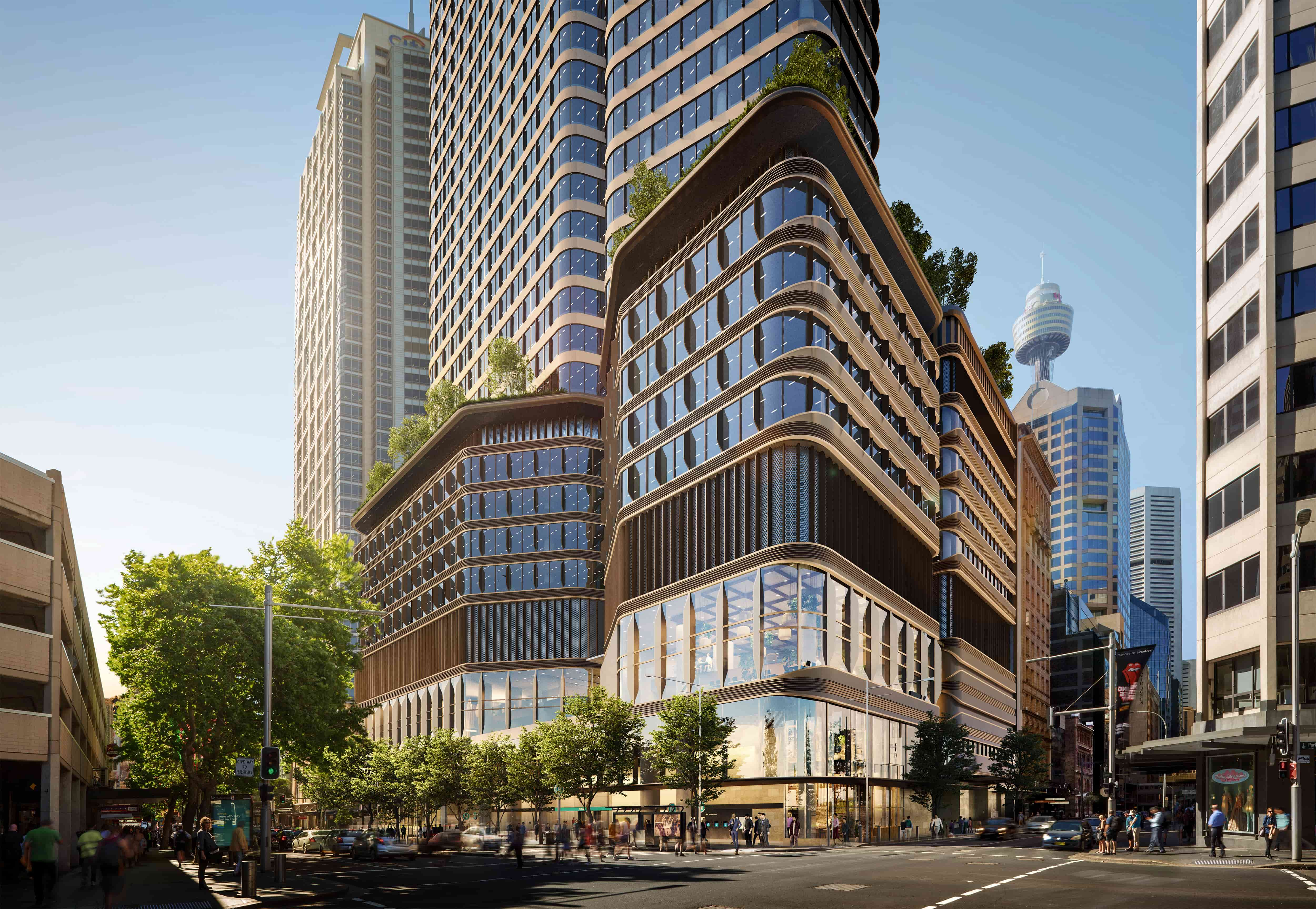
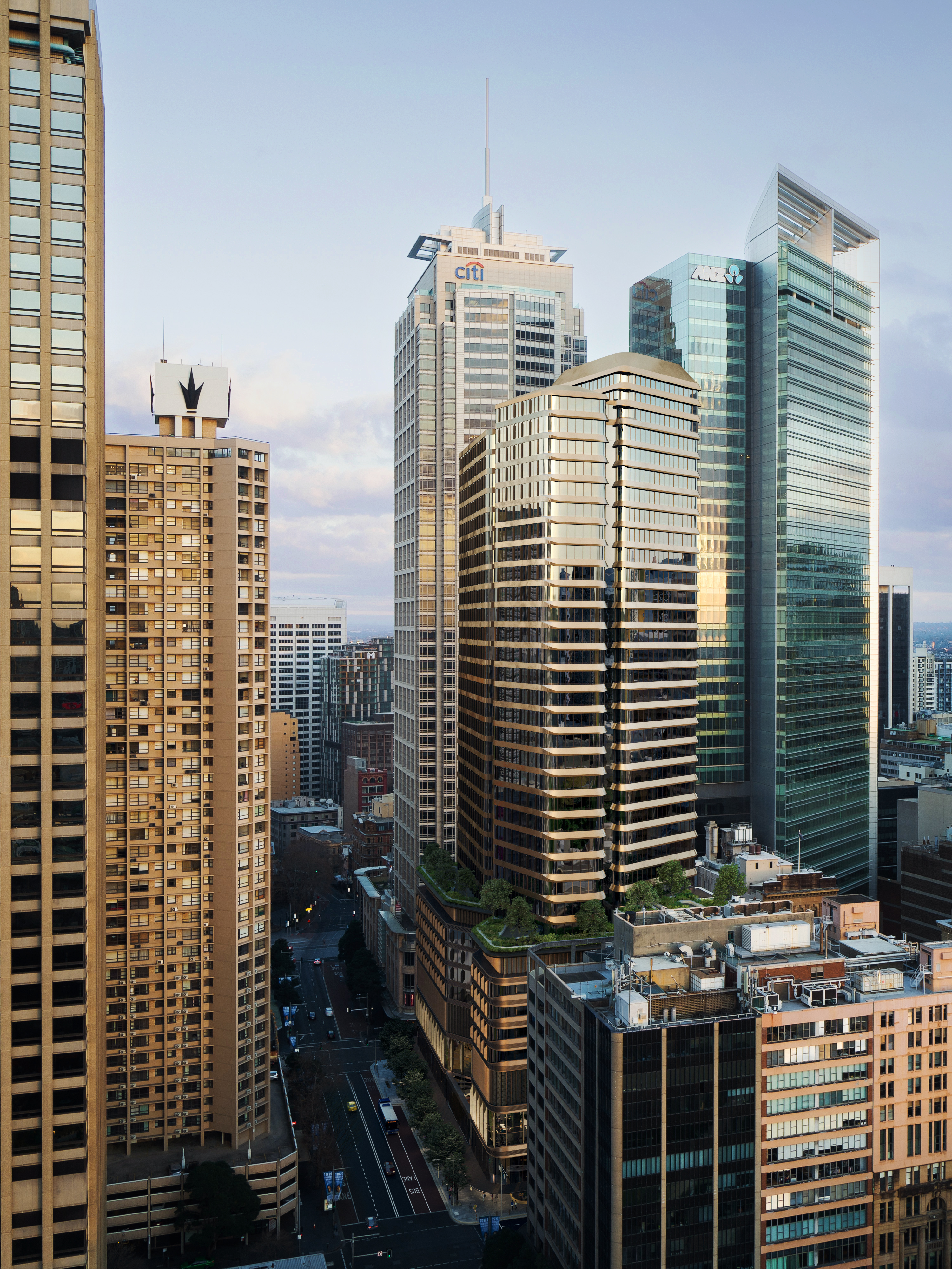
Parkline Place streetscape
Parkline Place, Sydney

Tenant Information Manual

Building Technical Specifications

Mechanical Services

This section covers air conditioning, mechanical ventilation, and aspects of the Building Mechanical System (BMS).

The mechanical system serving the typical office floors of the building is a combination of an active chilled beam (ACB) system for the perimeter zones and low temperature air volume (LTVAV) system for the centre zones.

Connection interphase to base building BMS must be discussed with the Building Management Team prior to any HVAC mechanical services works commencing in the fit-out.

During your fit-out, please provide your Project Manager with detailed plans showing the location of all staff, equipment, and lighting so the heat load and the usage of all areas can be determined. The Project Manager will also need to provide these plans to the Building Management Team’s preferred air conditioning consultant.

Ductwork modifications must be minimised to maintain straight duct runs, the use of flexible ducts need to kept to a minimum with bends kept under radius of 1.5 diameters.

Areas which are highly partitioned or have floor to slab partitioning must have sufficient return air grilles to allow return air to traverse the above ceiling space when partitioned doors are shut.

Tenancies on multi-tenanted floors may require either acoustic security transfer ducts across the tenancy dividing partition or return air grilles in the tenancy wall to the core corridor and corridor ceiling grilles; to allow the return air from the tenancy to leave the tenancy and return to the false ceiling level to return to the return air riser.

Air and water balancing of fit-out works must be performed by approved balancing contractors. The final balancing detail must be reviewed by the base building services consultant.

Parkline 6

BUILDING TECHNICAL SUMMARY

BUILDING TECHNICAL SUMMARY
End of Trip Facilities End of Trip Bike Parking of approximately 200 bikes.
End of Trip Amenities including showers, lockers, toilets and ironing facilities are located on Level 1 and can be accessed via the Castlereagh Street entry.
Parking and Amenities 37 car parking bays available within the Automated Vehicle Parking System (AVPS).
6 parking bays within the loading dock for loading vehicles (1 x MRV, 2 x SRV and 3 x B99).
Loading Dock The loading dock is accessible via Castlereagh street and comprises of a turntable system and can cater for a medium rigid vehicle of up to 8.8m.
The dock is level and therefore any vehicles with heavy loads will require a tail lifter to deliver the goods to the loading dock.
All access to the loading dock will only be permitted via pre arranged access on the online booking system.
Loading Dock Height Loading dock height 3600mm.

Air conditioning, Mechanical Ventilation
and Building Automation System (BAS).

Type
Information
Air Conditioning
Thermal performance of facade Glare control blinds and adequate spatial provision for future tenant blackout blinds. Automated blind system that forms part of the façade performance. Tenant override is available.
  • 2 x York MaxE Centrifugal Chillers R-134a
  • 5 Low Rise and 5 High Rise AHU's supplying Variable Air Volume (VAV) boxes – office floors
  • Condenser water supplied to retail tenancies for water cooled PAC units
Each floor will be served by multiple air-handling zones with 3 perimeter zones with a maximum perimeter thermal control zone size of 85m² and a nominal perimeter depth of 4m and two internal zones with a maximum zone size 120m².
Perimeter zone depth 3.5m
Chilled beam parameters Nominal size: 1800mm
Target Air Pressure Drop: 75Pa
Cooling Primary Air Temperature: 12°C
Chilled water temperature: Flow 14 – Return 17.5°C
Tenant Condenser Water Loop Condenser water loop with minimum capacity of 25W/m2 NLA cooling (31.5W/m2 heat rejection)
Connection valves at each floor sized to allow minimum 62.5 W/m2 floor NLA
The tenant cooling water plant will be provided with 100% redundancy of the system equipment design (except pipework) and
operation.
Tenant Supplementary General Exhaust General exhaust system with blanked off connection on each floor.
Minimum allowance of 0.25 L/s/m² NLA with take-off sized at 0.625 L/s/m² per floor.
Tenant Supplementary Toilet Exhaust Combined base building and tenant toilet exhaust system with blanked off connection on each floor.
To AS1668.2 (2012) plus an extra allowance of 0.2L/s/m² NLA with duct connection on each floor sized for 0.5L/s/m².
Tenant Supplementary Outside Air Tempered outside air riser system with blanked off connection on each floor for connection of a tenant supplied outside air fan to supply allowance of 0.3L/s/m2 NLA with take-off sized at 0.75 L/s/m2 per floor and comply with AS 1668.2 (2012).
Additional provision of Western facade louvre space for connection of a tenant supplied outside air fan to meet tenant requirements above the minimum provisions supplied by the outside air riser system (except for Level 5). This additional air provision must be tempered.
Internal Conditions
SUMMER | Dry Bulb Temperature (°C) 22.5°C +/- 1.5°C
SUMMER | Relative Humidity (%) 40 - 60%
WINTER | Dry Bulb Temperature (°C) 21.0°C +/- 1.5°C
WINTER | Relative Humidity (%)

40 - 60%

WINTER | Lobby Dry Bulb Temperature (°C) 18°C +/- 1.5°C
SUMMER | Lobby Dry Bulb Temperature (°C) 26°C +/- 1.5°C
Ambient Design Conditions
SUMMER | Ambient 32°C DB / 23°C WB
WINTER | Ambient

7°C DB 

Base Building Cooling Towers sized on 24°C WB

External Design Conditions
SUMMER | Dry Bulb Temperature (°C) 32.5°C
SUMMER | Wet Bulb Temperature (°C) 23°C
WINTER | Dry Bulb Temperature (°C) 7°C
Tenant Condenser Water System Capacity
Cooling Capacity (NLA) (W/m²) 20W/m2
Heat Rejection (NLA) (Wm²)

20W/m2

Water Allocation (NLA) (L/s)/m2 Levels 7 to 18 - 1 L/s
Levels 2 to 6 - 1.4 L/s
Water Temperature 28.5°C in / 34°C out
Internal Loads
Population Density Podium (L5-L8) 1:10 sqm

Low Rise (L10-L21) 1:8 sqm services and 1:8 amenities (subject to tenancy fitout)

High Rise (L22-L35) 1:8 sqm services and 1:8 amenities (subject to tenancy fitout)
Lighting (W/m2) 10
Outside Air | Minimum (L/s/person) 11.25
Controls tolerance Temperature control will be calibrated for open plan with temperature sensors to be located on ceilings.
Outside air An additional 50% above AS 1668.2 (2012) minimum requirements via base-building systems.

Appropriate filtration to AS1668 together with CO2 monitoring.
Maximum Noise Levels
Office areas (NR) 45
After Hours Air Conditioning
AHU | Whole Floor ($/hour) + GST $50 plus gst
Normal Hours of Operation of Air Conditioning Plant 7:30am – 6:00pm Weekdays
Zones Per Floor
Number of Zones There is a minimum of 4 zones per typical floor with a maximum zone size of 600m2.
VAV's No of VAV’s per floor dependant on NLA
General Exhaust Riser
Capacity | Average per Floor (L/s) 0.2 l/s/m2
Capacity | Maximum for One Floor (L/s) 0.1 l/s/m2
Capacity | Toilet Exhaust (L/s per floor) 0.1 l/s/m2
Supplementary Fresh Air Riser
Average per Floor (L/s) 0.3 l/s/m2
Maximum for One Floor 0.75 l/s/m2
Return Air Through Ceiling Space to RA Riser Yes
Building Monitoring and Control System
Type Controlworks
Distech Controls Building Management Control System
Availability for Tenancy Monitoring 
(subject to approval)
Yes
Building Envelope Glazing
SC Maximum 0.28
U Maximum (w/m2K) 2.6

Electrical, Security, Communications Systems

The electrical and security systems provided by Investa are designed to be tenant friendly, enabling efficient general servicing and substantial and regular fit-out alterations, with minimal inconvenience.

Prior to any demolition works, your Project Manager must check existing cables (power, data and communications) in the tenancy and obtain approval from the Building Management Team for any isolation or cutting of these cables.

This is to avoid accidental damage to existing base building cables, and impact to base building equipment operations. If the Building Management Team have not been advised and proper authorisation not provided to the main contractor, it will be the Lessee’s responsibility to restore damaged services.

The building primary power supply shall be from the Ausgrid Triplex HV network infrastructure to the substations located on Basement 1 and Level 9.

Backup generators will be provided to support the building load on loss of supply. Lighting will be via energy efficient LED luminaires.

An Electronic Access Control System (EACS) and Closed Circuit Television (CCTV) system will be provided throughout. The CCTV system will provide real time coverage of high risk areas and recordings shall be stored for 60 days.

Tenant Lighting

Lights are controlled from group switches.

Tenant Distribution Boards

All electrical circuits and GPOs must be numbered (circuit number and distribution board number) and the distribution board permanently labelled as appropriate. The load across phases must be balanced.

Wiring

All wiring run in ceiling spaces, including the central service corridor, must be supported on trays or catenaries, or clipped to the slab and bundled by means of cable ties.

No wiring whatsoever will be allowed to lie on the ceiling grid or tiles, be clipped to the sprinkler pipe work or run in the data cable trays.

To assist you with the cabling of power and communications cabling from the core area services, cupboards to the tenancy area facilities have been provided and are mentioned below.

Design & performance parameters
Tower
Power supply
Substation Arrangement Ausgrid Triplex 'City Type' Chamber Substation on Basement 1 and Level 9.
Capacity (kVA) 3000
Configuration Parallel
Feeder Arrangement 2 Feeders
Main switchboards Main switchboards will be located in the Lower Ground Main Switch Room and are to be constructed to minimum Form 3b as per AS 3439.

Additional capacity of 20% spare circuit breakers spaces and busbar expansion will be available subject to approval by the Landlord for the connection of additional tenant loads.
Bulk metering Tenant cost if required
Metering Authority metering for each commercial tenancy is available within the core on each level. Tenants to provide and install billing grade meters. Provision has been made for bulk metering at the Main Switchboard if requested by multi-floor tenants.
Energy metering will be provided with separate metering of power and light consumption via the building Energy Metering System (EMS).
Risers House and tenant services risers are located on all levels within the core.
Tenant Power Supply
Determined by relevant (NLA)(VA/m2) 50VA/m2
Standby power
Type of Drive Diesel
Number of Sets 1 (located on Level 9)
Rating 1650kVA
Operation Arranged for automatic operation upon loss of normal supply, but with decision making by in-house SCADA system.
Control PLC control enabling flexible operation upon total loss of supply and during power restrictions
Fuel Storage 12 hours at full load
Base Building Standby 100% essential services
100% Tenant Condenser Water loop
1 lift per riser
50% house light and power
Carpark Ventilation system
Tenant Standby Power Capacity - 
Determined by relevant NLA (m²)
Standby power available subject to building management approval
Tenancy floor cabling facilities
In ceiling cable tray throughout core corridors Yes
Core and perimeter conduit droppers from ceiling to skirting duct. Yes
Ducted Skirting N/A
Other Systems 2 off general communications riser
Telephone Cabling
Incoming Cable Location Lower Ground
MDF Location Lower Ground
Pairs per Floor 1 pair 10m² Determined by relevant NLA (m²) 
Building Lighting
Lighting Type
Tenancy Lighting
Average maintained level of luminance (Open Plan) (lux)
Fittings
Emergency and Exit Lighting
Compliance (Standard) AS2293.1
Tenant Fittings Central monitoring system.
Type Clevertronics computer monitored
Typical office power
Tenant provisions 40 VA/m2 which is in excess of the PCA Premium Grade Matrix.
Distribution boards 2x tenant distribution boards will be provided on all office levels constructed to form 2Bai configuration. Tenant distribution boards are sized to 1 pole per 15m2 of NLA. All power sub-circuit cabling and circuit breakers by tenant.
Cable reticulation Tenant cabling can be reticulated via the access floor, or coordinated and reticulated in ceiling with base building services. No skirting duct is provided.

Cable trays for tenant services are provided within the core. The tenant is responsible for reticulation of tenant services within the NLA.
Typical office lighting
Tenant provisions General office lighting consists of diffused LED sources with dimmable control.
Interior lighting Lighting type to be LED high efficiency.
Average commercial floor plate troffer lighting level of 320 lux and uniformity of 0.5.
Task and additional supplementary lighting by Tenant.
Lighting control system Lighting control system comprising of motion sensors within the open plan office and back of house areas.

Lighting to be addressable by zone to meet sustainability requirements with a lighting control panel on each floor.
Emergency and exit lighting LED emergency and exit lighting will be provided in accordance with AS 2293 and BCA requirements via a monitored emergency lighting system.
Security and Access Control System
System Features
Manufacturer Integriti
Card Type HID Corporate 1000 48 Bit complex
24 hour/7 day monitoring from Security Desk Yes
Time lapse VCR/DVR Recording Yes
Tape Image Retention Period 2 Weeks
Extent of System (Areas Covered)
Car Park After Hours Yes
Building After Hours Yes
Lift Control After Hours Yes
Fire Stair Door Locking and Monitoring Yes
Plantrooms Yes
Loading Dock Yes
Closed Circuit Television (CCTV)
Building Entry and Exit Points Yes
Common and Public Areas Yes
Car Parks Yes
Loading Docks Yes
Goods Lift Yes
Car Park Lifts Yes
MATV System
TV Channels Digital
Radio Digital
Antennae and Satellite Dish
Provisions available (subject to review and consideration of existing installations) Yes
Communications
Main Distribution Frame 
(pairs per floor)
Intermediate Distribution Frame
(on floor, pairs per floor)
Infrastructure
Risers Riser access to the base building is to be provided on all floors which are secured and accessible by authorised personnel only.
Main security control room Level 3
Equipment headend CCTV head end equipment to be located in the building MDF Room, with connectivity to the Integrated Communications Network (ICN) and Integrated Services Platform (ISP).
Access control system
Base building access control system Electronic access control provided to Building main entry/exit points, loading dock entry, lifts, security control room, major plant rooms and equipment rooms, building management office and end of trip facilities.

Video intercoms with remote door release will be provided at the loading dock.

Audio intercoms with remote door release will be provided within all fire stairs.

Access card readers are multi-technology readers.
Office tenant access control system The base building access control system contains provision for multi technology card readers to permit integration of a tenant access control system.
CCTV system The CCTV system to provide general coverage to the following areas:
Main public areas / lobbies, automated vehicle parking system loading dock, goods lift and points of entry and exit.

Hydraulic Services

The hydraulic services consist of the following systems:
  • Sewer drainage
  • Grease waste drainage
  • Hot water service
  • Cold water service
  • Fire hydrant & hose reel service
  • Sump pumps
  • Gas service
  • Downpipe and roof drainage
  • Dedicated cooling tower supply
  • Sanitary plumbing
  • The operation of plant and equipment is monitored by the BMS.
  • Stormwater and sub-soil drainage
Design and Performance Parameters
Provisional Services on Office Floors
Trade Waste Service 
(Grease Stack available on all levels)
Yes
Soil and Waste Services
Sanitary stacks available on all levels
Yes
Cold Water Service
Water risers adjacent to stacks with isolation valves
Yes
Floor Coverage for provisional services Entire Floor
Other
Hydraulic risers Located at the core
Base building toilets/EOT showers Toilets, urinals, sanitaryware (including tapware) to have auto sensor for touchless solution and smart command.

Cold water and hot water to fixtures. Thermostatic mixing valves to be provided to hand basins and showers in all female and male amenities (including the end of trip facilities).
Tenant hydraulic provisions Cold water: Ø25mm valved and metered connection.

Sewer: Ø100mm sewer capped connection and Ø100mm vent capped connection. Additional Ø100mm sewer capped drainage tee for future tenant connection.

Trade waste: Ø100mm trade waste capped connection and Ø100mm vent capped connection.
Terraces Cold water point (x1), Irrigation water point (x1)
Metering Base building water meters for tenancy monitoring and billing purpose.
Tenant water storage To be provided by tenant
TIM Graphics
FIRE SERVICES

Fire Services

The building is protected by a combined sprinkler and hydrant system designed to AS2118.6-2012. The fire pump and tank room is located in the Basement. Automatic fire sprinklers will be provided throughout the office floors with a single dedicated sprinkler valve assembly located within fire isolated stairs at each level that will permit floor by floor isolation to facilitate tenancy modifications. Fire hydrants are provided at the fire stairs together with the on-floor hydrant provided on the floor plate to maintain the floor coverage.

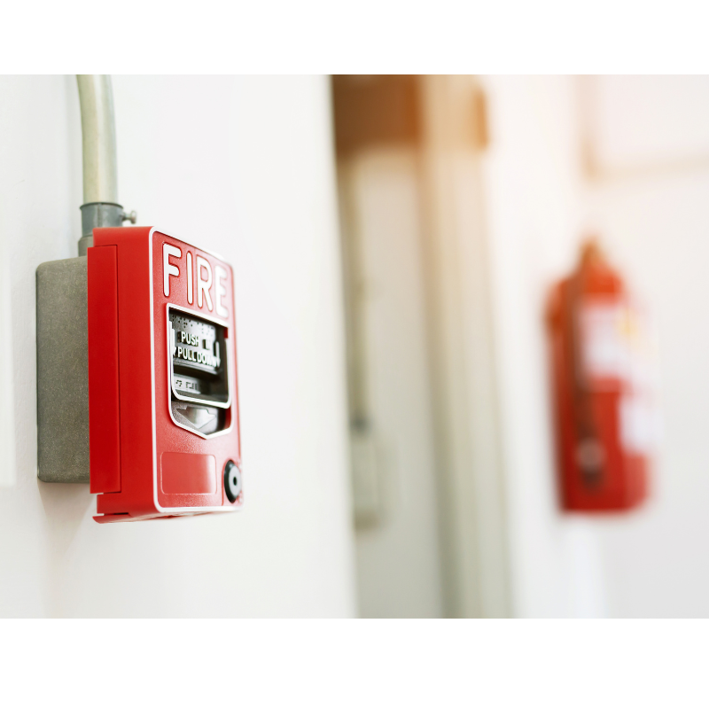
Detectors to AS1670.1 and EWIS speakers to AS1670.4 are provided. Warden intercom phones, manual call points and portable fire extinguishers are provided at each level / zone adjacent to the exit stairs. The base building fire panels are located in the fire control room at Ground Level.

Smoke System

Addressable Smoke detectors interfaced to the base building main fire monitoring system are mounted above each fire exit door and return air riser. These detectors are sensitive to dust and smoke which may be generated as a result of fit-out works. The Project Manager shall notify the Building Management Team in writing when dusty or smoky works may take place so that the detector(s) may be isolated. A Fire Impairment Form must be completed and lodged prior to any isolation taking place.  

Any charges incurred from Fire Brigade attendance for false alarms associated with fit-out works will be charged to the Project Manager. Under no circumstances are smoke detectors to remain isolated overnight after works have been completed.

Hose Reels

The hose reel cupboard adjacent to the fire stair door must remain accessible from the fire stair. All parts of a tenancy must be reachable by a hose reel. The Project Manager will arrange for additional hose reels to be installed to achieve this if required.

Coordination and notification to the Building Management Team is required in the event of Hose reel shut down being required.

Note that access to the aforementioned fire stairs from each level of the tower is not available at any times (unless there is an emergency).

Emergency and Exit Lighting

Emergency and exit lighting is installed on an open plan basis to comply with safety requirements. As a result of the tenancy fit-out, further emergency and exit lighting may be required, and any such additional lighting is at your expense and must comply with safety requirements.

Whilst Management will undertake 6-monthly emergency exit light testing, it is your responsibility to install service and repair exit lighting. Investa can arrange this on your behalf and this sundry charge will appear on your monthly rental invoice.

A certificate of compliance for the tenancy area Emergency and Exit Lighting must be supplied as part of the tenancy Fire and Essential Services documentation.

The following table contains the design parameters of the fire and emergency systems.


Emergency Warning and Intercommunications System

EWIS speakers are provided below ceiling generally for the office floors and visual warning devices for specific plant rooms as per BCA and AS1670.4-2015.

At least one power amplifier per zone with spare capacity for the connection of 20% additional speakers as part of tenancy fitout / future works.

Warden intercom phones (WIP) and manual call points (MCP) are provided adjacent to one of the fire exits in every emergency management zone.

Sprinkler System Isolations

  • Drain downs must be kept to an absolute minimum. Any drain downs must receive approval from the Building Management Team with no less than 24 hours' notice
  • Drain downs left overnight or for an extended period are conditional on approval by the building insurers and adherence to any requirements imposed by the insurers. Any costs associated with this approval and subsequent conditions will be the responsibility of your Project Manager.
  • Drain down and refill operations will only be performed by the building preferred contractor, without exceptions.

  • The existing sprinkler system will be retained in service whilst new pipe work is being installed, and all new pipes must be cut over during one drain down. Sprinkler systems must be refilled and operational overnight and on weekends.
Design & performance parameters
Tower
Sprinkler installation
Standard Combined sprinkler and hydrant system to AS2118.6-2012. Sprinkler hazard to AS2118.1-2017.
Average Spacing per head Determined by fire consultant
Sprinkler Head Type Underside of ceilings fitted with white two part adjustable semi-recessed escutcheon or fully concealed
Office Hazard Rating Ordinary Hazard 1
Car Park Hazard Rating Ordinary Hazard 2
Retail hazard rating Ordinary Hazard 3
Goods Lift Lobbies Yes
Floor Fire Stair Doors Yes
For operation of mechanical plant under AS1851 2005 Yes
Isolation valves A single dedicated sprinkler valve assembly located within fire isolated stairs at each level that will permit floor by floor isolation to facilitate tenancy modifications.
Fire monitoring system
Type Automatic FIP and EWIS System
Other Sprinkler system, hydrant/hose reels and extinguishers installed on each floor
Smoke Detectors AS1670.1
Emergency warning and intercommunication system
EWIS At least one power amplifier per zone with spare capacity for the connection of 20% additional speakers as part of tenancy fitout / future works.
Warden intercom phones (WIP) and manual call points (MCP) are provided adjacent to one of the fire exits in every emergency management zone on every floor per BCA and AS1670.4-2015.
Type Simplex
Code Compliance AS1670.4
Maximum Area per Speaker on office floor standard! AS1670.4
Hydrant and Hose Reels
Number per Floor (In accordance with BCA and NSWFB Spec 10) 2
Performance AS2419.1
AS2441
Location Fire mains and fire hydrants located within fire isolated stairs at each level. On-floor fire hydrants to ensure full coverage of the building based on 30m hose and 10m spray as per BCA requirements.

The fire hose reel is provided within 4m of each exit where required by FRNSW and PCA at each level.
Fire indicator panel Main panel: Located in the fire control room on Ground Level.
Tenant alarms: Interface with the base building fire panel via the base building fire detection loops.
Security interface: Interface with the base building fire panel.
Fire extinguisher Located on each floor as per AS:2444-2001.
Tenant requirements No installations are to obstruct, impede or affect the fire services of the building. Should any design have such an effect, the tenant will be responsible to re-design and for any re-fitting / make-good costs, as required, and only following Landlord approval.

Lift services

Design & performance parameters
Tower
General Lift Parameters
Lifts provided by back-up power 1 per riser
Security No
Power System Solid state direct drive with gearless machines
Number of Lifts Per Rise
Podium rise 3
Low Rise 6
High Rise 6
Goods Lift 1
EOT lift 2
Entry lift 1
Speed
Podium (m/s) 1.6
Low Rise (m/s) 2.5
High Rise (m/s) 6
Goods Lift 2.5
EOT lift 1
Entry lift 1
Duty (kg)
Podium Lift 1600
Low Rise 2000
High Rise 2000
Goods Lift 2500
EOT lift 2000
Entry Lift 1200
Average Waiting Interval (sec)
Low Rise <30
High Rise <30
Population Density (person/m² NLA)
Low Rise 1:12
High Rise 1:12
Dimensions (mm)
Door Opening Size - Width 1200
Door Opening Size - Height  2400
Internal Car Dimensions - Width  1650
Internal Car Dimension - Depth  2000
Internal Car Dimension - Height 2800

Communications

The integrated communications network system will comprise a combination of passive structured cabling and active networking to support the transmission of information throughout the building.. Dual diverse pathways to the MDF are used to reduce the risk of downtime to the network.
Design performance parameters
Tower
Building distributors Two Building Distributor Rooms are provided for multiple telecommunication carriers as required for base building communications and tenant services with direct access to the base building and tenancy risers.
Risers Two (2) Communications Risers for House Services and MATV/DAS distribution.
Three shared communications risers for tenant use.
Master Antenna Television (MATV) MATV backbone to be provided for distribution of all available Free to Air (FTA) and Foxtel channels to all tenanted floors.
Mobile telephone system 100% mobile coverage to be provided to NLA and common areas
Wireless system Wi-Fi provided to the main lobbies, entry and end of trip facilities.
Telecommunications Prior to any telecommunication equipment installation, the design will need to be reviewed by our consultant, Telco Access Authority, at tenant cost. Please refer to section 9.7 Building Services for Consultant details or reach out to the Parkline Place Management team.
New penetrations for fibre/cable runs will need to be reviewed by the buildings structrual engineer and fire rated.

Distributed Antenna System (DAS)

Providing a quality mobile phone coverage experience within a building is achieved using a dedicated building system known as a Distributed Antenna System (DAS). The system is installed throughout the building, including cables in risers and ceilings, and antennas below the ceiling within the tenancy, lift lobbies and public areas. The service is then delivered via dome antennas and will be visible when installed below the ceiling. In some instances, the antennas may have been placed above the ceiling.

Due to the topology of these systems, any damage to an antenna or cable within the ceiling may have an impact on a larger portion of the system. Damage to the system results in not only a deterioration of mobile performance but also the entire sector.

Consequently, the preservation and adjustment of the system to accommodate a specific tenant fit out is critical. A DAS is highly specialized equipment and should not be handled by a standard electrician or builder.

The most recent version of the Mobile Carrier Forum (MCF) guidelines published in November 2018 represents the latest set of operator guidelines outlining details of performance and testing requirements, installation standards and PIM expectations as a point of reference for DAS works. The MCF is updated every few years to reflect the changes in technology and should be reviewed in accordance with these guidelines.

Tenant Activity Impact
  1. Modification of floor fit-out Changes to the fit-out may limit the quality of coverage throughout the floor, particularly if new walls are being erected for offices and meeting rooms. For example, antennas being isolated in enclosed area may significantly impact the performance of the DAS throughout the floor.
  2. Relocation/Damage to Infrastructure Undertaking any tenant fit-out or refurbishment resulting in antennas being placed above the ceiling, removed, or damaged will lead to coverage gaps and deterioration of the ‘sector’ of the DAS within the building. Similarly, it is not uncommon for coaxial cable to be cut or bent beyond the prescribed bend radius which can result in cables having to be replaced in their entirety to achieve the required DAS performance levels.
  3. Passive Intermodulation (PIM) Interference A more subtle activity may result in the creation of interference on the system whereby the materials of nearby items including fit out materials and furniture (particularly metal) can negatively impact the performance of the system. Typical issues come in the form of emergency lights, sprinklers, metal lockers, etc. This is generally not malicious damage, but it will result in a deterioration of performance. Typically, any DAS works on a given floor should be at the back of a fit-out process to allow for PIM optimisation once all the new structures are in place.
Process to Limit Impact
As with all utilities the preservation of the DAS is paramount. All costs associated with retaining the DAS in its’ operational state during and immediately after the fitout will be borne by the fitout contractor and their respective client. The buildings DAS consultant, Wireless Coverage Solutions, must be engaged, at tenant cost, prior to tenant fitout to ensure reliability.

DAS Systems with a Lead Operator – Tenant Fitout
Refer to the specific license between the landlord and the operator for specific process and notification periods.

Typically, the process will progress as follows.

  1. Provide notice to the operator of the upcoming changes to the floor including relevant information – typically RCPs and partition plans will provide the operator with the information required to move forward.
  2. The lead operator may choose to pursue works themselves and will likely provide a quotation, or they may be willing to refer the work to a qualified party depending on the scope and the operator’s policies
  3. As the system is live it is likely that works will need to be completed within an ‘outage’ period, usually at night or out of hours, where the operator will power down the system for H&S reasons.
  4. The operator may put in place documentation or testing regimes in line with their requirements.
Please contact the Parkline Place management team should you require any further information. Further DAS related technical support is available from Wireless Coverage Solutions Pty Ltd.

Base building integrated services platform

An Integrated Services Platform (ISP) will be provided to consolidate the monitoring and supervision of relevant building systems including metering, air conditioning, emergency lighting and lighting control.
The design of the ISP will use digital technology and industry standard open protocol communication standards to provide a unified approach to the integration of systems across the Integrated Communications Network (ICN).
Design and performance parameters
Building intelligence The ISP will be used for displaying, monitoring, archiving, reporting, trending, scheduling, and supervision of interfaced systems.
Interfaced systems Uninterrupted Power Supply (UPS), Common Lighting Controls, Specialist Lighting Control, Emergency Lighting, Electrical Metering, MSB Switchgear, Power Monitoring and Correction, Generator Monitoring, Energy Monitoring System, Security Access Control, CCTV, Fire System, Vertical Transport, Hydraulic systems (Water) and Blind Control System.
Reporting Data storage for the purpose of providing standardised data access for customisable dashboards, graphics, trending, reporting and diagnostics applications.
Tenant fitout Tenant to pay for integration costs required for updates of the Integrated Services Platform (ISP).

Building management and control system (BMCS)

The design of the Building Management and Control System (BMCS) will use digital technology with Bacnet open communications for interoperability with other services and integration with the Integrated Services Platform.
Design and performance parameters
Building intelligence Energy efficiency control strategies, interoperable functionality with other services.
Coverage Monitoring and control of HVAC systems.
Interface with proprietary systems High Level Data across the integrated communications network.
Reporting Alarms, status and trends

Metering

The design of the Metering System will use digital technology with open communications protocols for interoperability with other services and integration with the Integrated Services Platform.
Design and performance parameters
Coverage Metering of Electrical Services, Mechanical Services and Hydraulics Services in accordance with Green Star and NABERS requirements.

Building Mechanical System (BMS)

The BMS provides control and monitoring of all major air conditioning and ventilation plant, in addition to monitoring of selected, important aspects of other services.

A system of centralised Building Automation System. The system is fully automatic at each level of operation.

Workstation A work station complete with high resolution monitor, keyboard and mouse is located in the Building Management Office.
Power Supply The BAS is powered by house power.
External Monitoring The BAS system may be accessed remotely as required.
Sensors Space temperature sensors have an accuracy of +/-0.3°C.
Alarms Alarm points are capable of assignment of at least three priorities to allow grading of alarms from critical to non-critical. Email is sent to Building Management.
Scheduling All systems are provided with time scheduling on a seven-day basis with holidays capable of being programmed
 at least one year in advance.
Control Point Adjustments

All control points are fully adjustable from the central workstation.

Logging Some system points are provided with both trend and event logging facilities.
Reports Generated as required
Graphics Graphics are provided to designate systems using real time values, dynamically updated at least every 90 seconds.
Services The BAS monitors or controls the various building services as follows:
  • Mechanical Services
  • Air conditioning is provided with Direct Digital Control (DDC) system. The central plant is controlled by a selection of master sensors from various floors.
The following programmes are provided:
  • Optimum start-stop of main air conditioning plant
  • Outside air economy cycle initiation and control
  • Optimum chiller sequencing of all chillers
  • Boiler sequencing.
  • After hours air conditioning is logged by the BMS system and includes the number of hours run, the time, date and floor for which it is required. AHAC can be activated with an authorised access card swiping over the AHAC reader located next to the directory board on Bligh Street Entrance.
  • Electrical Services
  • Lift Services
  • OTIS REM lift monitoring
  • Fire Services
  • The BAS monitors the alarms and sends an email to the Building Management Team.
  • Hydraulic Services
  • The BAS monitors the alarms and status of the hydraulic services.

Other Specifications

Design and Performance Parameters
Ceiling
System Mineral fibre ceiling tiles
Grid 1500mm x 600mm
Floor to Ceiling Height 2.7m
Slab to Slab 3.75m
Tenant services zone 150mm total for at least 80% of the NLA
Contiguous floor plate Central core arrangement with optimised column grid.
Typical office ceiling module Suspended mineral fibre ceilings tiles at a 1200mm x 1200mm module, with flush set suspended perimeter plasterboard ceiling margin to floor plate.
Parking
Capacity 40 car spaces
Access Via 183 Castlereagh Street
Maximum height clearance Car park area = 2 metres
Loading dock = 3.6 metres
Bicycle parking Level 1
Amenities
Accessible Toilets All Levels
Shower Facilities End of trip

Automatic blinds

All office blinds are automatic.

Tenants are to ensure that no objects are placed against the window and avoid placing any objects that obstruct or interfere with the automatic blind operation as this could cause damage.

Any damage caused from improper use or obstruction will be the cost of the Tenant and charged accordingly.

  • Long press down (for down)
  • Long press up (for up)
  • Short press of the same to stop the motion.

Should you need to replace the blinds in your tenancy, below are the specifications for the automatic blinds used at Parkline Place.

Supplier: Solis Products Pty Ltd
Model: Blinds 205 Silverscreen
Make: Verosol


PSOD Blind Control Description v3 20240704 AsB (1)

Blind Control System

Local Control

Local control switches are mounted on the columns or lift core adjacent to the zones they control.

There is 1 switch per zone in most cases, some zones have multiple please refer to blind control drawings.

Switches have Up / Stop / Down functionality giving the user the ability to place the blind at any level preferred.
Long press for moving Up/Down, short press for Stop.

The Local control can be used when the zone is not deployed under automatic solar heat gain and glare control. This priority to automatic functions can be changed to priority user override functions if required at any stage.

The local control will reset to the automatic position 2 hours (settable) after switch press.

Automatic Function

The blind control system utilises multiple factors in automatic mode.
• Shadow Management
• Weather Station on the roof measuring actual light level
• Cloud Oktas supplied by the Bureau of meteorology (cloud cover level)
• Outside temperature (optional)


Shadow Management

The system employs a shadow model that shall provide a status for each zone. This is driven from a 3D model of the building and surrounding area supplied by CPB. A data file is created where each zone is sampled every 15 minutes to determine if any part of the zone has the sun shining directly onto it. A flag for the time is set. This data file shall be hosted on the shadow device. The system shall check each point once every minute to determine if the zone in in sun or in shadow.
The definition of “IN SUN” shall be ALL of the conditions below being met:
• sun above the horizon
• sun active on ANY PART on the zone (e.g. if the sun is on the west side of the building a zone on the east cannot be in sun)
• zone not in complete shadow due to the influence of surrounding buildings.

At this point IN SUN does not cover if the sun is above the brightness threshold.


Sun Brightness & Temperature Threshold


Brightness & temperature (optional) thresholds are set and used to drive the blinds using the following logic (consider zone not in shadow):
• If brightness level & temperature (optional) exceed threshold for at least the “above threshold” hysteresis period (adjustable) this will deploy the blinds to control solar heat gain and glare.
o Blinds stay at position unless shadow model confirms window group is now in shadow
or
o Brightness level or temperature falls below threshold for at least the “below threshold” hysteresis period raises blinds to 0%.
• If shadow model confirms windows groups are in shadow blinds will raise/stay at 0% in automatic mode.
• If temperature is exceeded however brightness does not blinds will be at 0% in automatic mode (optional).
• If brightness is exceeded however temperature does not blinds will be at 0% in automatic mode.
Note:
• When sensor is in failure the system will use the cloud oktas level from the Bureau Of Meteorology in place of sun brightness.
For the blinds to deploy under automatic mode the zone needs to be not in shadow, over brightness threshold and over temperature (optional) threshold.

PSOD Blind Control Description v3 20240704 AsB (2)

Base Build Parameters

The base build system will be set with the following parameters.
Parameters
Metrics
Brightness threshold Above 40 klux
Brightness threshold below 30 klux
Above threshold hysteresis 2 minutes (120 seconds)
Below threshold hysteresis 15 minutes (900 seconds)
No sun/below threshold Blind 0% (open/up) - Local control active
In Sun / Above Threshold Blind 100% (Closed/down) – Local Control inactive
Cloud Oktas (if sensor failure) 1/8 Clear Sky (2 – 8 / 8 not over threshold)
Temperature Threshold East 20c
Temperature Threshold North 20c
Temperature Threshold West 20c
Temperature Threshold South 20c
Above Temperature Hysteresis 2 minutes (120 seconds)
Below Temperature Hysteresis 15 minutes (900 seconds)
Reset to automatic from local control 2 hours (settable) from switch press of relevant zone
Unless otherwise informed and processed.

Building Service Contractors

Outlined in the table below are the preferred base building consultants who we strongly recommend are engaged to design the services to your tenancy.

Engagement of these consultants is due to the extensive knowledge they possess on the existing building services. They may also be able to provide you with an opportunity to save on associated costs.

Please note: the below consultants will be engaged at the tenant’s cost to peer review any service designs prepared by others.

Services
Contractor Company
Contact Information
Access Control Securacore 1300 856 612
Auto Doors

Dorma Kaba

1300 362 022
BAS
BMCS Alerton 02 9648 6347
BMU A Grade Access 02 8213 7484
CCTV Heyday +61 2 9855 6614
Cleaning Services Ozland Group Solutions 1300 144 114
Communications Heyday +61 2 9855 6614
Data Commissioning Willow Technology

Selwyn Rees:
srees@willowinc.com

DAS TriloG Simon Ramm: 0425 123 334
Digital Twin/BIM

Martin Tomasson

0493 023 300
Doors Grosvenor Engineering 02 9758 9555
Electrical

DBS Consultants

+61 2 8313 7037
Emergency and Exit Lighting Heyday +61 2 9855 6614
Fire Services and EWIS Premier +61 2 8422 6888
Flooring Godfrey Hirst Australia 02 9757 7999
Glass Works Express Glass 1300 666 234
Handyman Edsring Property Maintenance 02 9904 8194
Hydraulic Services Axis +61 2 9708 5666
Hygiene Services Flick Anticimex 131 440
ICN/ISP Operational Intelligence +61 2 9648 6347
Indoor/Outdoor Plants Posh Indoor Plants 02 4733 3633
Lifts and Escalators Otis +61 2 8338 2700
Master Key System IKON Doors +61 2 9451 3511
MATV System Heyday +61 2 9855 6614
Mechanical Services Fredon +61 2 9475 9400
Security Services E Group Protective Services

(+612) 9561-3111

Thermograph Fredon Elecrical 02 9475 9400
Waste Removal Bingo 1300 424 646
Waste Treatment iTreat 1300 780 029
Window Cleaning GDP 02 9997 1999
Warden / Emergency Training Hendry 1800 875 371

Engineering Contractors

Services
Contractor Company
Contact Information
Mechanical Services DBS Consultants +61 2 8313 7037
Electrical Services DBS Consultants +61 2 8313 7037
Structural Engineering

Aurecon

02 9465 5599
Hydraulic Services Axis +61 2 9708 5666
Fire Services DBS Consultants +61 2 8313 7037
BMCS DBS Consultants +61 2 8313 7037
DAS Wireless Coverage Solutions 1800 318 039
Certifier

Philip Chun

02 9412 2322
Telecommunications Telco Access Services 02 4724 9017

Building information modelling (BIM)

In conjunction with Willow, Parkline Place has developed a digital twin which records and makes available all aspects of the building’s equipment, operation and maintenance information – within an intuitive 3D environment to drive more efficient planning and operations.

To get the most out of the Digital Twin and assist with integrating information created during your tenancy fitout, we ask that you review the following guidance and familiarise yourself with the process outlined in Appendix 4.

BIM Costs: Tenant to pay for 3D modelling and COBie data collection costs in relation to the fit out, including integration with the landlords base building 3D models and data.
Requirements
Description
General requirements The tenant shall at a minimum undertake
the following for the Level of Development
(LOD) in accordance with Appendix 7 for
their fitout:
  • Architectural and below ceiling services to be designed to a minimum LOD 200.
  • All services design and in ceiling walls/baffles above ceiling to be designed to a minimum LOD 300.

In general, the models require clear indication in 3D of all alterations of the base build structure and building services reticulation. There is no requirement to model loose furniture (workstations are required to be modelled). Furniture that has been installed in a manner that forms a wall/pathway is also required to be modelled.
Design and construction The Tenant shall provide 3D models for the following disciplines as well as a Federated file in Revit and Navisworks (or similar, to achieve IFC 2x3 output) for all disciplines. These shall be submitted at least once during the Design Phase for landlord approval processes, finally in an as-built format recognising the requirements, within two weeks following the completion of works.
  • Fit out Approval Architectural Fitout Design, Structural Fitout Design, Mechanical Services Design
  • Electrical, Communications & Security Design, Fire Services Design
  • Hydraulic Services Design Fit out As-Builts
  • Mechanical Services Shop Detailed Design & Construction Electrical, Communications & Security Shop Detailed Design & Construction
  • Fire Services Shop Detailed Design & Construction Hydraulic Services Shop Detailed Design & Construction
  • Structural Steel Shop Detailed Design & Construction (if applicable) Access Floor/Ceiling Shop Detailed Design & Construction (if applicable).
As built verification On completion of the works, the tenant shall ensure the 2D/3D As-Built drawings/models have been verified for accuracy by a surveyor (or similar) nominated by the landlord to confirm the location of the installed items of the fit-out space (above suspended ceiling panel and floor to ceiling partitions only where alteration of the base build design building services has occurred).
The tenant is responsible for the accuracy of their model submissions and shall bear the costs to rectify their models where they are not in accordance with the fitout as-built.
Asset data The naming conventions for Equipment Asset ID numbers (i.e. unique numbers for equipment) and requirements for Asset Data are yet to be finalized.

At a minimum, the essential asset information (i.e. Name/Type/Manufacturer/Asset ID etc.) for key maintainable assets (i.e. VAVs/Light Fittings/Sprinklers etc.) will be required by the Tenant to be delivered in spreadsheet format (.xlsx or .xml format).

It is a requirement that the Equipment Asset ID numbers in the register match the relevant equipment within the 3D model for verification and linking of information. The Tenant is to label equipment in accordance with the Landlords naming convention.

The final deliverable spreadsheets are to be included in the O&M Manuals with all relevant spares, warranties, commissioning information and related data.
Software and formats

The Tenant shall author all design elements within Autodesk Revit (or similar) and export Revit (.rvt), Navisworks (.nwc) and Industry Foundation Class (.ifc 2x3) model exports, coordinated with the base building models.

The Tenant is responsible for all software/hardware required to comply with MBS including obtaining current Autodesk Revit licenses and procuring suitable PCs/Laptops.

BIM costs Tenant to pay for 3D modelling and COBie data collection costs in relation to the Fitout, including integration with the Landlord's Base Building 3D Models and Data.
Integrated tenant fitout works
General requirements In addition to the items listed in section 19 above, Tenant Fitout requirements shall comply with the following items.
BIM execution plans Compliance with the following project documents Equipment & System Naming Conventions lnvesta FM Data Requirements Level of Development (LOD) Modelling Element Author (MEA).
Coordination and collaboration The tenant shall allow for regular 3D design model submissions and coordination meetings with the Base Building Design and Construction team to identify key interfaces and any potential issues/ clashes.

The Tenant shall nominate one of their drafting team as lead BlM coordinator, who is responsible for ensuring all team members are following project guidelines for BIM integration and who shall attend weekly design BIM integration meetings as required.
BIM costs Tenant to pay for 3D modelling and COBie data collection costs in relation to the fitout, including integration with the Landlord's Base Building 3D Models and Data.